I see that there are many topics in the support forum concerning this issue, but I have not seen an exhaustive discussion of maximum output capacitance for integrated power modules.
Search results for ‘max output capacitance’ - Monolithic Power Systems’ Technical Forum
I am using an MPM3833C as a supply regulator for AU15P Xilinx Artix UltraScale+ 0.72V VCCINT core voltage rail. The expected load is ~1A. I have over 500uF of capacitance on this rail, per Xilinx recommendation from their PCB design guidelines document.
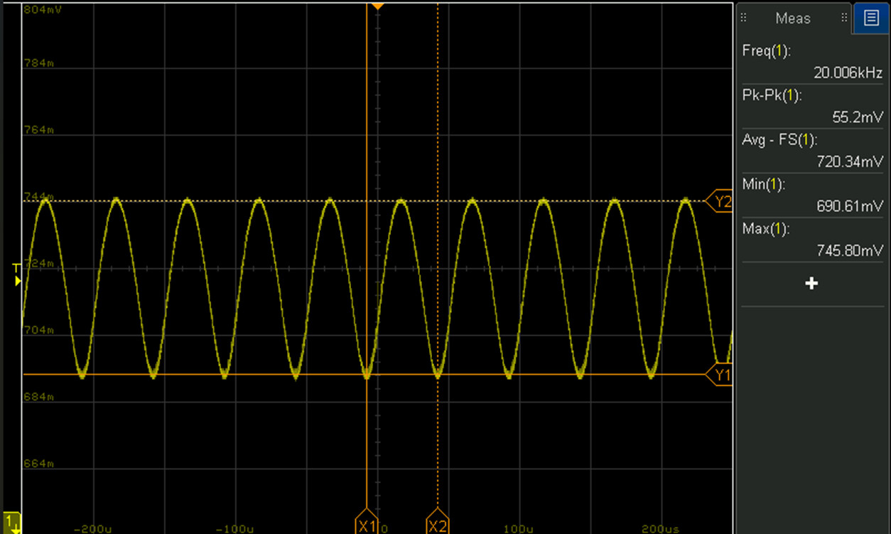
I am observing that the output is unstable and continuously oscillates at 20kHz with 50mVpp amplitude under 1A load. Regulation is marginal for the Artix voltage rail requirements. I can replicate the behavior on an EVM3833C evaluation board by installing 6x 100uF Murata MLCC capacitors in parallel with the output. After observing this oscillation, I notice in the MPM3833C datasheet that the max operating output capacitance is 100uF.
One post on the support forums suggests that COT devices are inherently intolerant of excess output capacitance.
Meanwhile, MPS has several reference designs intended to power an Artix UltraScale+ AU10/15P, which all use multiple-output COT regulators. I don’t see any discussion of maximum output capacitance in the datasheets, but nothing in the test report documents suggests that tests were done with anything other than the 44uF on the module evaluation board, significantly lower than the Xilinx recommended capacitance.
Another project team within my organization has had success with using an MPM38222 as the 0.72V core voltage regulator with the same AU15P Xilinx FPGA. Notably, this regulator uses peak-current-mode control, as opposed to COT-mode control. Also, a separate post on the MPS support forums states that the MPM3834C can support up to 1.5mF of output capacitance. So I will try one of these modules for my application.
My questions are the following:
- Is there a recommended single-channel regulator module for the Xilinx AU15P FPGA core voltage? Many MPS regulators do not list a maximum output capacitance in their datasheets, so it is difficult to determine which will be suitable. If there is no recommendation, I will try to move forward with the MPM38222 or MPM3834C.
- Some sources state that inserting a small series resistance or inductance in the output before the bulk capacitance will isolate the bulk capacitance from the control loop, but I have not seen a procedure for selecting appropriate values of resistor/inductor. Is there an app note for this? I am hesitant to add series impedance to a digital voltage rail.
- The question of maximum output capacitance has come up frequently on the MPS support forum, as noted above. Is there an app note discussing the impact of large bulk capacitance on the module control loop? It is common with FPGAs to have core voltage rails with several hundred uF of capacitance, so it would be easier to select appropriate regulators with a better understanding of the effect of large bulk capacitance, especially with COT-mode regulators.