Hello, I created design with MPM3695-100 to power FPGA.
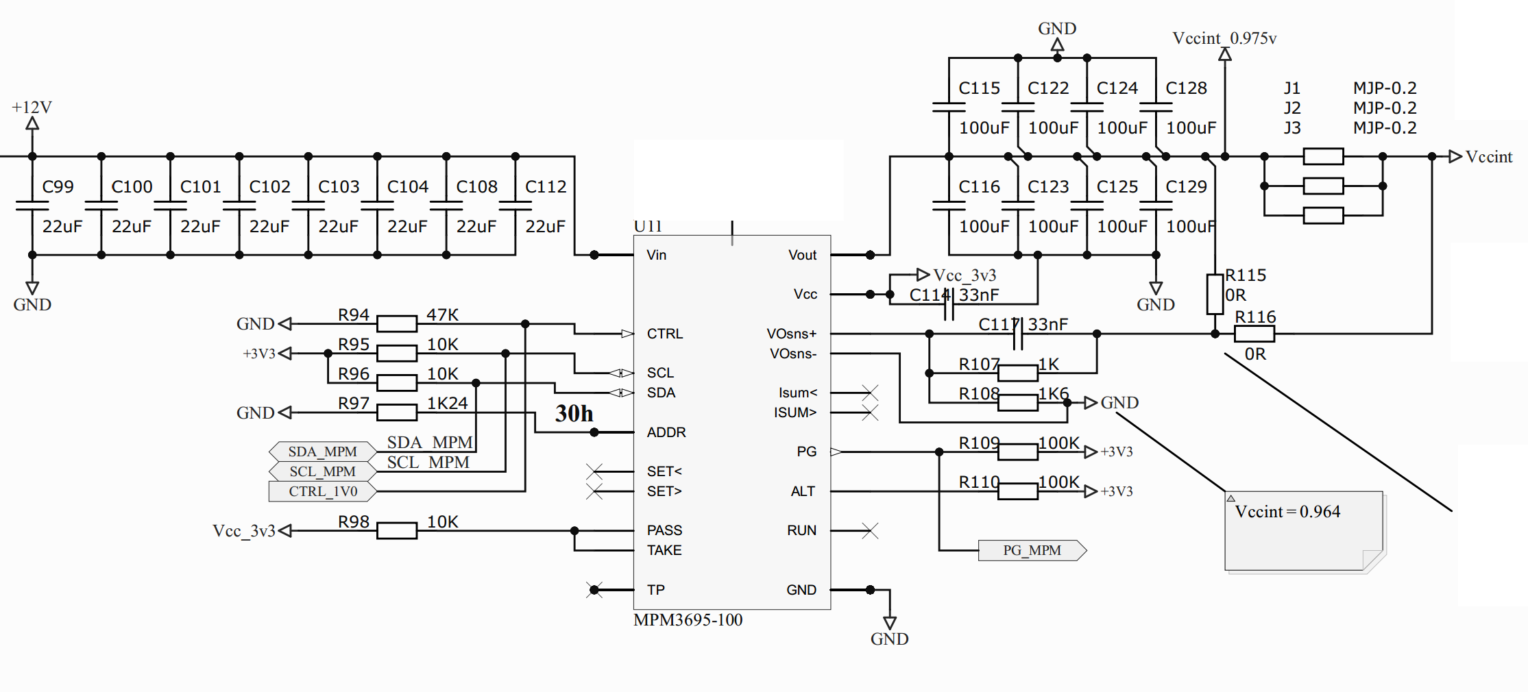
Now i implement my board with schematic shown below and DC doesnt starts.
For first time i want test my design and dont connect them to FPGA. For testing R115 is placing, but R116/J1/J2/J3 DNP. When i power it up with +12V, at output i see 0.3V.
I find issue that i connect TP to each other, because reading I2C saw me some bad output data like I=5A for my unconnected output.
So i unsoldered IC, cut path, reball and resoldered my IC. Now i see 0.030 V in output. When i connect resistor load, output voltage being 0V.
I2C read and write correctly when i disconnect TP.
So i have 2 qestions:
- Is my scheme correct and able to work?
- Can i corrupt this IC with connecting TP to all together? Not to GND or VCC. Will resoldering new IC help?
UP
I checked all regs and values of elements. When i start powering my board with 12V, PG becomes high, ALT is is normal, STATUS_WORD reg say all work normally. Vout from regs is 0V, but 0V is lower then 0.6V minimal output value of MPM3695 and i want to see “output under voltage” error. I think IC is working not by datasheet and is bad, but so are working at least 4 IC which i tested.
Please help me! I want to use your products in my projects.
P.S. Initial values are Vin=+12V
CTRL input we control over ATtiny by 3 state(Z) or 0.
FB resistors R107=RC0603FR-071KL
R108=RC0603FR-071K65L
I am a beginner and where i can get complete detail about articles about inductors for beginners?
Wurth has a bunch of articles “the trilogy of magnetics” IIRC.
reminder
I am a beginner and where i can get complete detail about articles about inductors for beginners?
Hi @yankun.k
Our sincere apologies on the delayed response to your post. Thank you for utilizing the techinical form.
Your schematic seems correct, what were you connecting to the TP pin initially? It is recommended to simply float them not tie them.
Kind Regards,
Nouman
Hi @reznikhauf
Thank you for utilizing our MPS Technical Forum for enhancing your understanding for inductors.
Please refer to Understanding Power Inductor Parameters | Article | ,
It should assist you further in learning more about inductors and their uses in DCDC converter devices.
Kind Regards,
Nouman