1: What is the allowable external load current on your Vcc LDO regulator? I need to power a few pull-ups and small glue logic. It would be nice to use, but I don’t want to compromise the regulator’s performance. (also does the current limit depend on input voltage? I’m using nominally 12V in)
2: Pg 23 references “R4” and “C4” (the schematic on pg 1 has no RefDes. None of the schematics in Fig6-10 include an R4) Where can I find them in a schematic?
3: Table 1 gives suggested values for Cff for a few output voltages, but there are no equations or general solution for R1, R2 and Cff as a function of Vout. Can you provide this?
Also do the recommended values for Cff depend on the amount of output capacitance or out nominal load current?
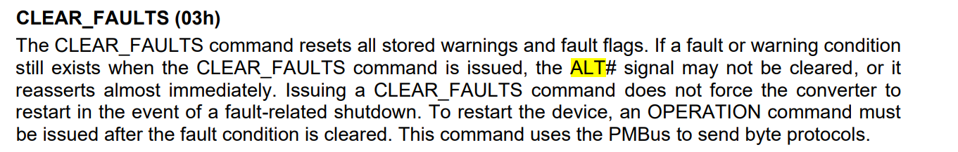
4: How persistent is the ALT# signal? Is the CLEAR_FAULTS command the only way to reset it, or does toggling the power, control line or some other input do it?
5: Please define “Hiccup” and “Latch Off” modes.
6: While you are at it, please describe the meaning of all the registers. For example, searching on “MFR_HICCUP_ITV_SET” I find out this register is 1 byte read/write with error correction, at address D8h and that the “Store_user_all” command saves it, but nowhere does it describe what it actually means or does…
Hello Ralph.Wolf,
I answered the majority of your questions and will update you on 2 and 6 when I get more information.
- Generally do not recommend loading it. The most would be as shown for the PG pin.
- I will update you after getting more information.
- R1 and R2 are mentioned in the following equation
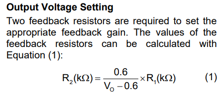
The CFF is a general recommendation for adjusting the gain bandwidth and improving stability. It could be adjusted based on your behavior. We do not have further equations for sizing. An online search can provide some more input into this.
5. Hiccup and latchoff are used for handling faults. Hiccup will repeatedly power off device until the fault condition has lifted. Latchoff will prevent an output.
6. I will update after getting more information.
1: isn’t really an answer. If you are going to provide a power supply pin for use with pull-ups and such, it’s traditional to spec it’s current capability in mA. Can you ask the design engineers what they are comfortable with?
I have a small amount of circuitry between this chip and my I2C controler that needs power to talk to the device. If I power it from the Vreg’s output, it creates a Chicken and Egg problem where I can only communicate with the device to configure it, when it is already configured sensibly.
Re 5: In Hiccup mode how often does it power the device back on to retry it? If the fault is still present how long before it shuts down again?
I’m seeing some modulation on the power supply output that could be explained by this Hiccup behavior, or it could be driven by variation in the current demand from downstream loads. If I know what sort of timing to expect from the Hiccups, it will help me identify the source.