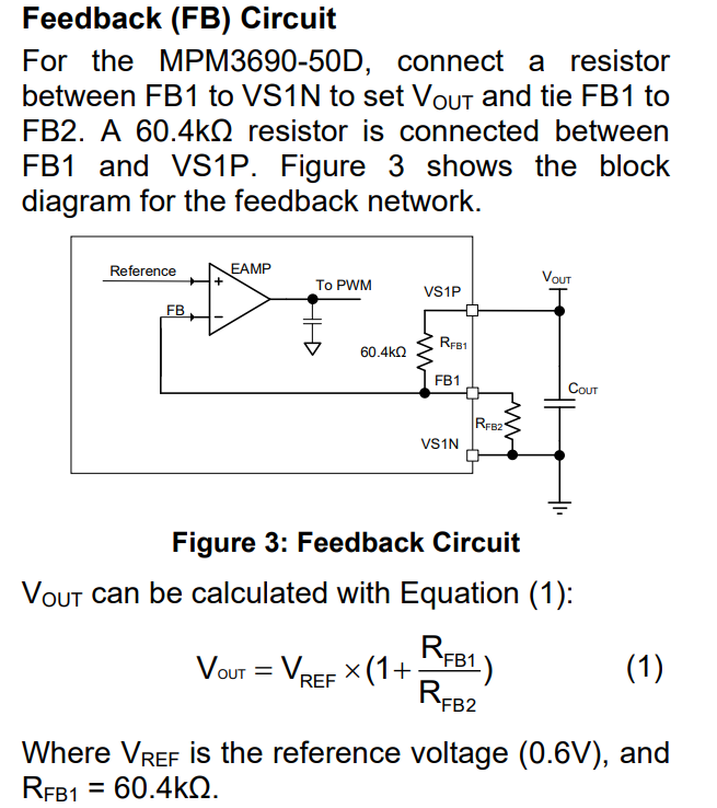
The “Internal” output is controlled via PMBus, while the “External” output is set to the desired voltage by adjusting the FB resistor value.
In the case of the “External” setting, the output is exactly matched to the voltage, but in the case of the “Internal” setting, the output is about 0.25V higher than the voltage.
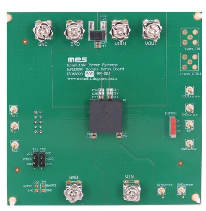
Test conditions
a. Using Bench Pro 4.0.
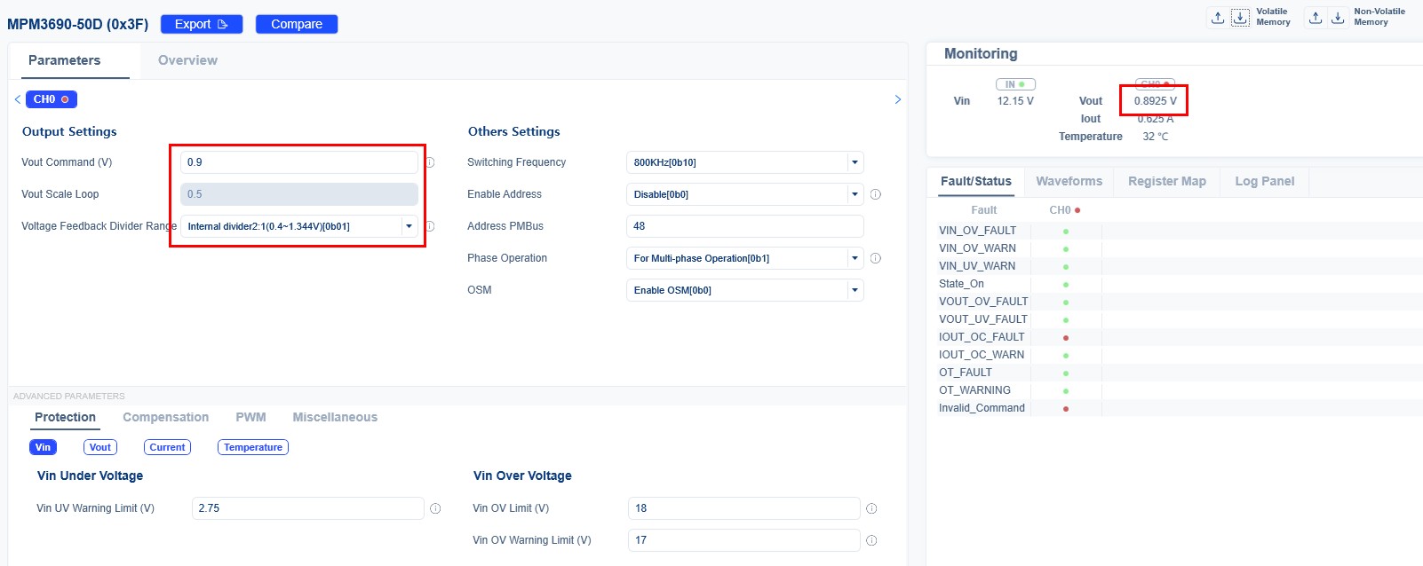
b. Internal divider 2:1(0.4V ~ 1.344V) : 0.5V //Scale Loop
c. Vout Command(V) : 0.9V
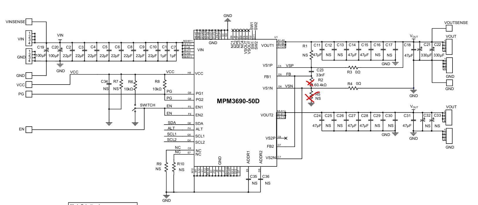
d. R2, R5: Not installed(Based on EVB circuit diagram)
A phenomenon in which the actual output voltage increases by 0.25 V compared to the “Vout Command”.
Thanks for providing these added details and clarification. This helps provide insight on what you are dealing with and the discrepancies between the external and internal divider settings.
I’ll discuss this with my team and get back to you soon. However, I am sure if you are using the internal dividers, you will want R2 populated. R5 is only used as an external resistor so it is fine to leave this unpopulated when using the internal dividers.
10 Ohms is the standard value that is shown when using the internal feedback resistor network when prompted to do so on the GUI. This is not stated anywhere on the datasheets specifically, but perhaps this should be the case.
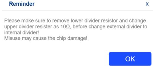
When setting internally, apply R-up as 10Ω among the FB resistance values.
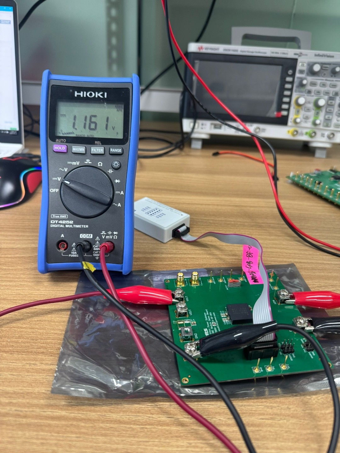
I assembled 10Ω to R2 in the circuit and tested it on EVM.
Test conditions: VIN=12 V, no settings change
Overcurrent and short circuit symptoms occur immediately upon 12 V input.
The message you provided is the same as the one I received. (This message was confirmed in the past when R2 was not installed.)
I assembled a 10 ohm resistor in R2 in the circuit, and the test results show that the R2 value is affected.
Please provide guidance on how to achieve normal output.
For more in depth and timely support, please fill out the following form and a ticket will be created for your case. Please let me know if there are delays in a response on this issue through this avenue. Here is the following link: