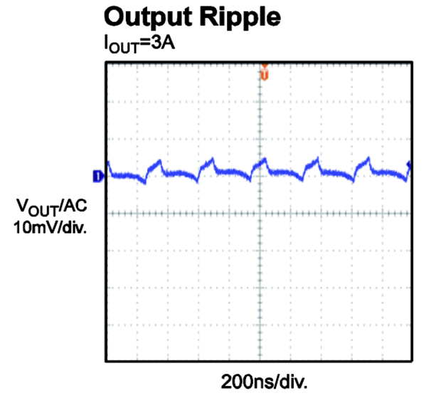
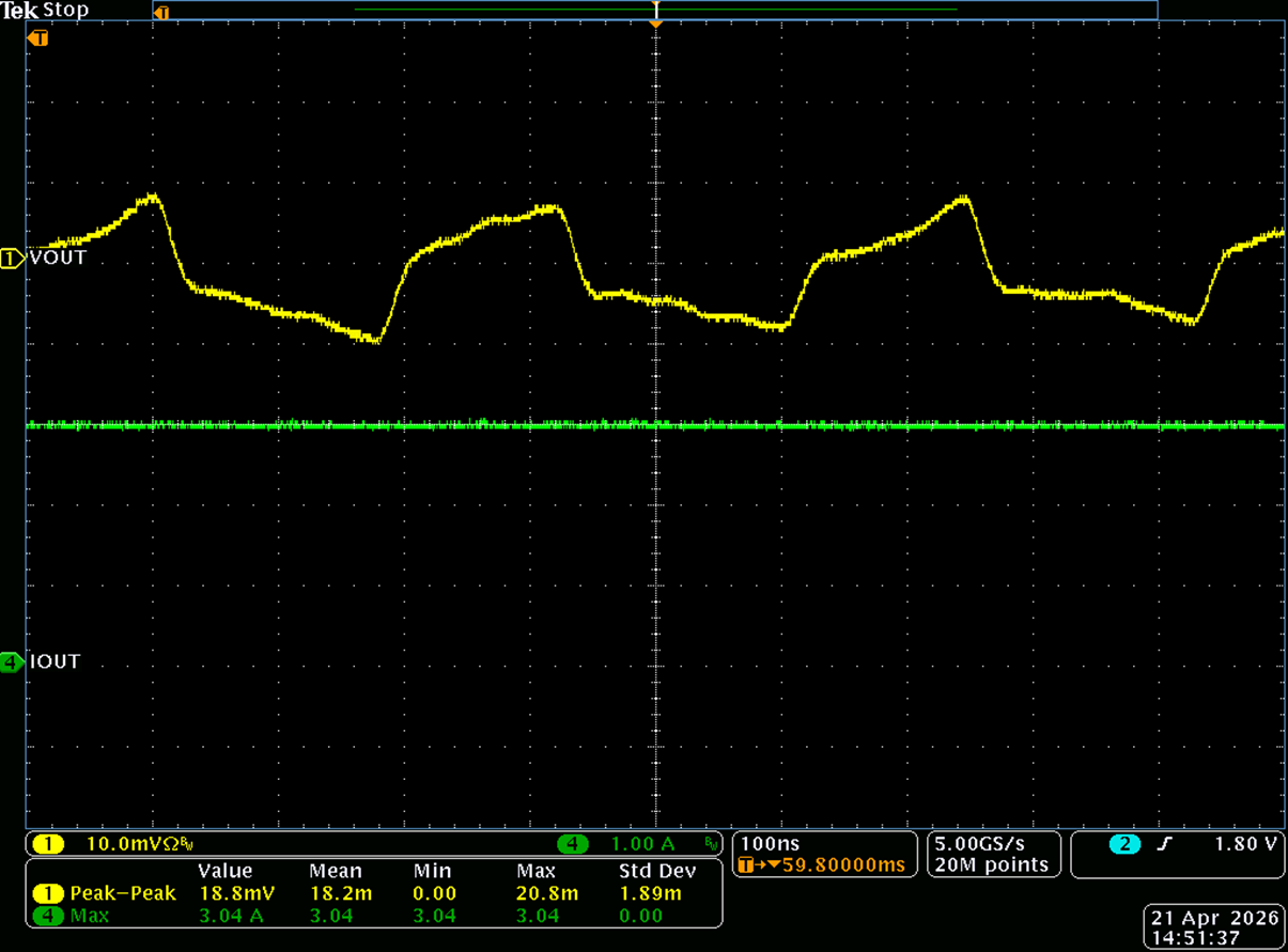
The ripple graphs in the datasheet and the EVM datasheet do not match, but are close in pk-pk amplitude.
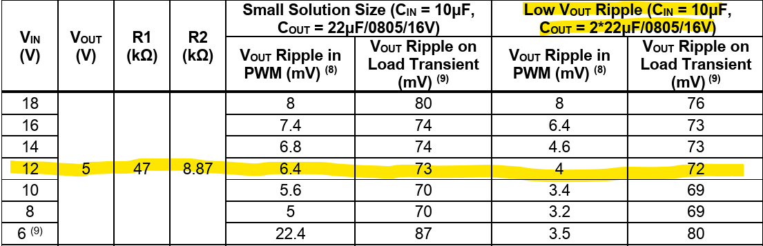
Referencing Table 1 in the datasheet, I reconfigured the EVM for 5Vout output.
My conditions are:
12Vin
5Vout
3A load.
I measure 18.8mVpk-pk ripple using a differential probe across a 2-pin header I installed on the EVM. I scraped away the solder mask on the VOUT plane and GND plane, so I could measure VOUT ripple with a P6247 diff probe from Tektronix. My bandwidth is 20MHz.
The changes to the EVM are as follows:
Changed R1 and R2 to 47k and 8.87k respectively to match the IC datasheet Table 1 conditions. According to Table 1 with these component values and a configuration of12Vin, 5Vout, 3A I should expect 4mV (I presume peak, so 8mVpk-pk).
Below is a comparison of the EVM graph and my scope capture. The waveshape is similar, but the pk-pk values I measure are 3x higher.
I have tried measuring with a single-ended 1Mohm probe, 20MHz BW, with a pigtail across the 22uF C2A as well.
Is there an optimal point on the EVM that I should be measuring to match the performance shown in the IC and EVM datasheets?
Thank you for your support.
Hi,
Thank you for posting on the MPS Technical Forum.
Best practice is to measure across the output cap with a twisted pair and a differential probe.
18.8mV is quite large, but what ripple spec are you trying to meet?
Thanks,
Allison
Hello Allison,
Thank you for the follow up.
I did not use twisted pair to my probes, but I do have a Tek P6247 differential probe that connects to a simple 2-pin 2.54mm header across the output cap on the top layer. I have also tried a single ended, 1MOhm passive probe with the spring clip as well also across the output cap. The GND of the spring clip is inserted into an SMT pin receptable I soldered to PGND and the probe tip is on the 0utput side of the cap on the top layer. That is as close as one can be for ripple measurements
Both setups have BW limited to 20MHz and additionally the P6247 has DC reject on similar to the single-ended probe AC coupled.
In both cases I cannot replicate the ripple graphs of 4mVpp/6mVpp (EVM) based on the configuration shown in the datasheet. This is my target to match the performance shown in the MPS documentation (IC and EVM datasheets).
This has been set aside at the moment and I am looking at other devices.
I am confident in my setup, but I am always open to understand if I missed something. Can you confirm the exact setup/equipment/settings that were used to measure ripple in the above conditions? If it is simple to do, can you replicate using the evaluation module?
Thank you for your support.
Hi,
Do you get the same results using both of the methods you have described?
My first suggestion would be to use a twisted pair. You can easily make one if you’ve got wires and header pins. Then try that with the diff probe over the output cap. 20MHz should be ok to see the ripple here.
If the ripple is still an issue, it would be helpful to see Vin, Vout, SW, and Iout on one scope shot for debugging. I can take a look if you are able to provide this.
Best,
Allison
Hello Allison,
I am on business travel until the 25th, so I will have to follow up then.
Not implementing twisted pair shouldn’t be a concern given either probe (differential or single-ended w/ pigtail) are referenced directly across the output cap to minimize inductance in the measurement path. I will check anyway when I return, along with capturing a detailed waveform per your request.