A +5V output design with MPM3620AGQV-Z is causing trouble to downstream device when the main +12V supply voltage to the MPM3620AGQV-Z is cycled very fast, as can happen if the connector is experiencing contact bounce;
The MPM3620AGQV-Z design is per the datasheet and set for 5V; We have some failures related to cycling power to the system. After investigating, it looks like hot plugging, or relay contact bounce (the supply of +12V) is causing the MPM3620AGQV-Z to overshoot the +5V output by up to 1.5V (meaning the 5V rail jumps to 6.5V) for 10’s of ms before settling back down to +5V; This behavior does not occur all the time; It takes many tries to quick connect/disconnect the source +12V to see this overvoltage. 85% of the time the MPM3620A is well behaved with this make/break source voltage input voltage.
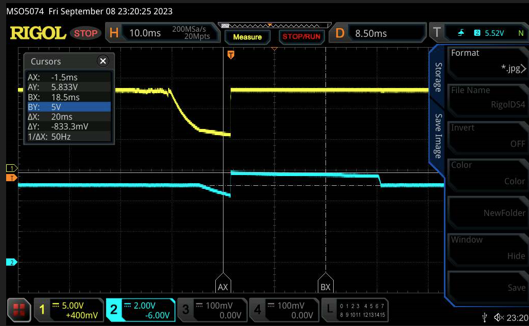
When the input voltage is presented peacefully, the MPM3620A performs as expected.
The load current is 0.5 to 1A.
CH1: Yellow trace, is 12V
CH2: Light Blue trace is 5V
Timebase: 10ms
Trigger: CH2, level 5.5V
In this screen shot the 5V rail is about 5.9V, after the 12V reconnects. It looks like the 12V falls to about 6V at its lowest point before rapidly connecting back to 12V source. This event apparently causes the MPM3620A to misbehave. I have captures when output of the MPM goes over 6V, which is causing electrical overstress to the down stream load. This is problematic and resulting in damages. Please advise.
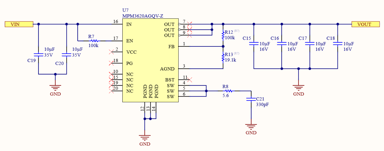
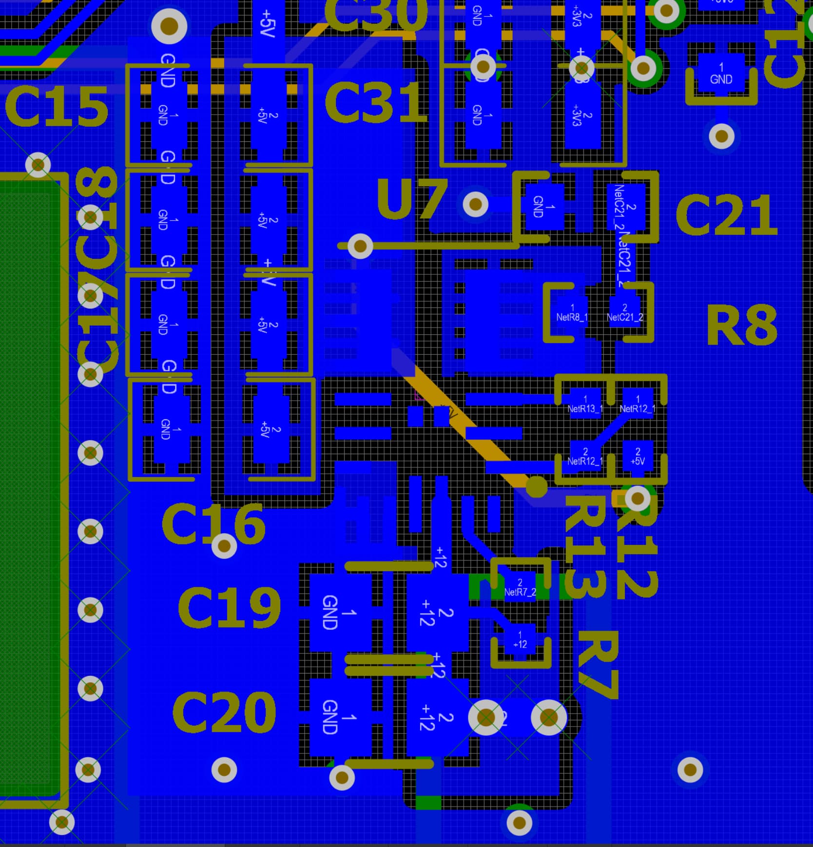
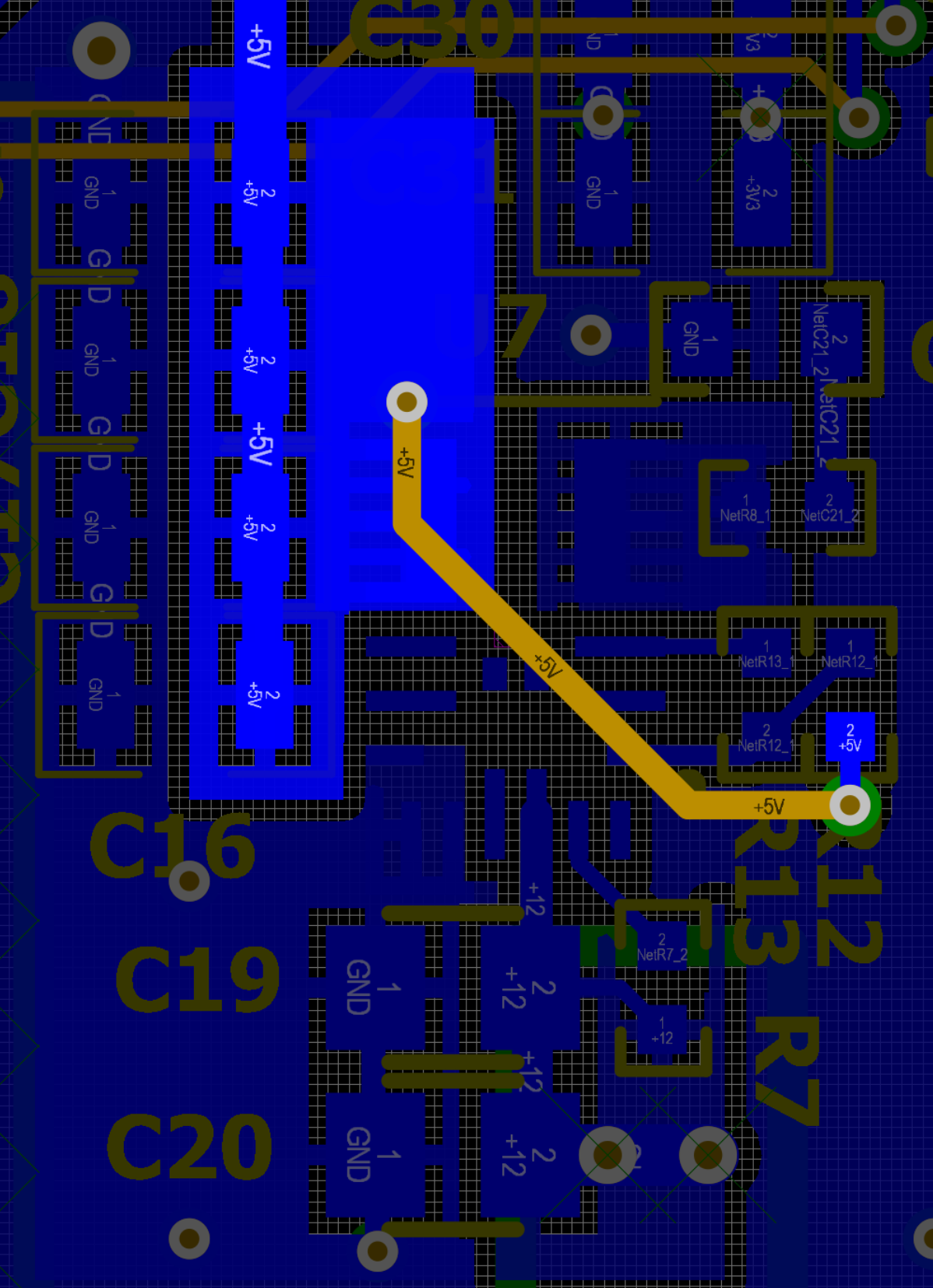
The MPM3620A can operate with Vin as low as 4.5V, so even though the input voltage drops to 6V it should be able to keep the output at, or very close to, 5V. To better be able to help, I would like to know how you got these waveforms, could you share your testing set up? It could also be helpful if I could see your schematic and PCB layout of our part.
Additionally, the MPM3620A has an EVB that you can request. It might be worth it to request it and see if our EVB exhibits the same behavior you are seeing.
The lab setup:
-Carrier board with MPM3620A
-50 ohm BNC cable with ground and hot soldered across nearby output capacitor (ensure high impedance probe / ground return lead not picking up EMI that distorts the true signal events)
-Rigol scope
-Lab Supply set for 12V (current limit is high enough to ensure zero brown outs or voltage sags)
-As explained in the initial post, I am probing the 12V source and 5V output rail of the MPM3620A;
-I am triggering (on 5V rail) 5.75Volts, single capture.
Thank you for sharing the above snippets. The schematic and layout look ok. The max D of this part is typically 83% and when Vin falls to 6V and is expected to give 5V it is pushing its limit. Maybe the combination of a fast input transient while being at max D makes the regulation slower. Try replicating this scenario when Vin falls to 7V, does the output voltage still have a huge spike and stays at that rise for 10ms?