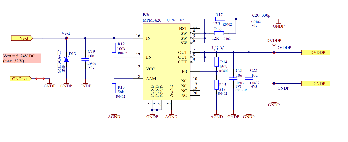
We have integrated the MPM3620 in our application to regulate an input voltage of 5 V–24 V down to an output of 3.3 V.
We have encountered multiple issues with the MPM3620:
Issue 1:
During the first tests using a 5 V input, after multiple power-on and power-off cycles, a short circuit appears between the 5 V input and the 3.3 V output. This condition recovers after the device has been powered off for some time. We measured the power-on behavior of the MPM3620, and it appears normal. The same PCBs were working fine for the first few days before this issue appeared.
Issue 2:
Occasionally, the output voltage is around 800 mV. It seems that some kind of shutdown or protection may be occurring in the regulator. This does not happen on every power-up, only intermittently. We have tried adding an external soft-start circuit, but it did not resolve the issue.
PIN connection question:
How is the PIN 15 connected internally? We measured that the PIN 15 appears to be connected to the 3.3 V output. Is this correct? We checked the PCB layout and confirmed that this connection is not present on the board. We also desoldered the MPM3620 and verified that there was no such connection externally.
Could you please advise on the possible causes of these unpredictable behaviors and how we can resolve them?
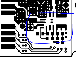
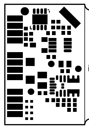
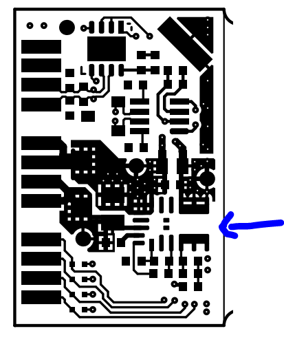
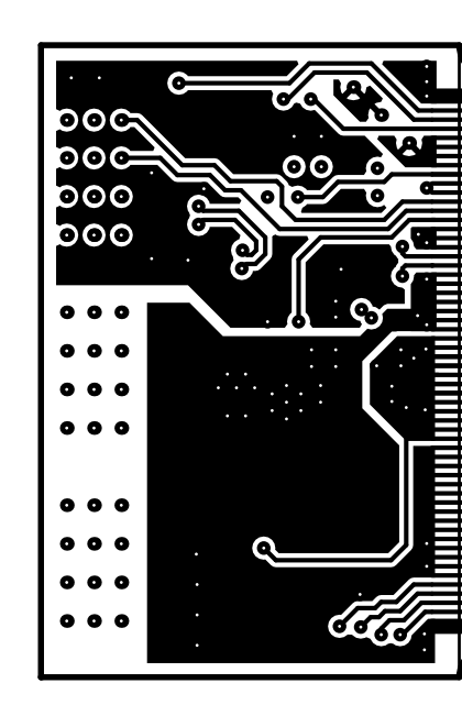
Please see the schematic and PCB layout below for reference.
Apologies for the delayed response here. A few questions given the description of these issues:
How widespread is this issue? Is this seen in multiple units?
If you have replaced the old MPM3620 module IC with a new MPM3620 module IC, does this issue persist?
In terms of the conditions in which this occurs, does this issue only occur when Vin = 5.5V? You mentioned your Vin ranges from 5V - 24V, so I am curious if these behaviors vary at a higher input.
What are the exact loading conditions here? Depending on what this may be, have you tried floating or driving the AAM pin high (above 2.5V)?
Would you happen to have any waveforms showcasing the described issues?
Would it be possible to send a clearer image of the layout implementation?
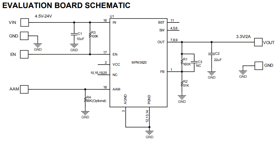
The primary differences between the schematic and typical application here are resistors R16, R17, and C20. Does this behavior persist when these components are removed?
If there is further instability even after this, I would recommend adding a NS for a feedforward capacitor in case further compensation is needed.
Since it has been some time since your initial post, please let me know if there have been any updates since. I await your response.
Thank you for your response.
below is answers to your questions.
How widespread is this issue? Is this seen in multiple units?
1. If you have replaced the old MPM3620 module IC with a new MPM3620 module IC, does this issue persist?
Ans: we have not tried replacing the unit as the issue is on multiple PCBs. The behavior is on each PCB is varying we are currently testing 11 samples simultaneously.
2. In terms of the conditions in which this occurs, does this issue only occur when Vin = 5.5V? You mentioned your Vin ranges from 5V - 24V, so I am curious if these behaviors vary at a higher input.
Ans: We have tested so far two separate Vin for our test 5 V and 12V. Vout was close to 650mV in some cases and others show short circuit between Vin and Vout. The cuurent consumption of 4 samples is with time incresing leading to short cirtcuit between Vin and Vout. These issues appeared with time. Beyond 12V Vin we have not tested yet.the issues are at both tested Vin present.
we have removed the MPM3620 in two PCBs and tested if the ASIC+sensor is the issue but withut the MPM3620 evereything is working fine and is also stable.
3. What are the exact loading conditions here? Depending on what this may be, have you tried floating or driving the AAM pin high (above 2.5V)?
Ans: MPM3620 is supposed to power a ASIC+Sensor which running @3.3V ~68mA. Do you think the load is too less? We have not tried floating or driving the AAM pin high yet. Removing R16,R17 and C20 did not improve the issue.
4. Would you happen to have any waveforms showcasing the described issues?
Ans: Which measurement would you want to see? I can measure and share.
5. Would it be possible to send a clearer image of the layout implementation?
Apologies for the delay in a response to this inquiry.
For more direct support for reviewing the layout and asking about internal IC architecture questions, please submit a ticket for more swift and detailed support: