Hi all
I’m using the MPM3515 to generate a 5V rail down from 9-32V input for a portable solution (battery operated either 12 or 24V batteries), so when trying to put the system in low power mode I’m want to reduce power consumption as much as possible.
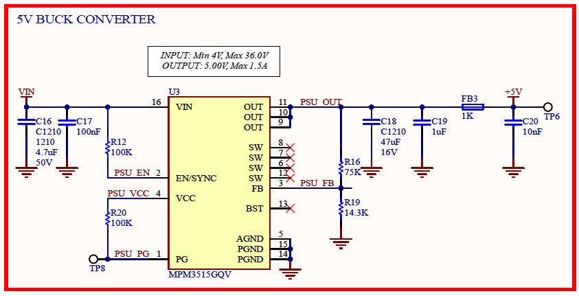
I’ve isolated all loads down the line after the 5V reg by removing FB3, so the only thing running on my board from the 12V input is the MPM3515, power consumption sits at ~15mA constant. If I remove R12 and leave EN/SYNC floating then the MPM3515 shuts down and the power consumption drop to 0mA.
What’s the best way to identify why the module is taking so “much” current? Is it because the voltage regulation is not as efficient at smaller loads? How can I improve this?
- Resistors are all 1%
- C16part number is CL32B475KBUYNWE
- C18 part number is GRM32EC81C476KE15L
- These are the first batch of prototypes for my design, I’ve assembled 5 PCBs and all measure about the same quiescent current ~15mA
Any feedback is greatly appreciated.
Thanks,
Martin
Hi Martin,
Interesting, the Iq for that module itself should be much lower.
When you try testing with power supply instead of battery, do you get the same Iq?
Best Regards,
Yu
Hi Yu, yes I’m testing with a regulated bench power supply with the output set to 12v. In my board I have removed everything down the line after the 5v reg and other ICs on the 12v have been disconnected as well.
I tried reflowing the MPM3515 again just to make sure it’s seated properly but nothing has changed. Again leaving the EN/SYNC to float turns off the regulator and the current draw goes down.
I’ve ordered another brand of caps and doing captures on the oscilloscope I don’t see anything wrong in the input or outputs in terms of ripple.
What’s else do you suggest I could try?
Hi Martin,
Thank you for your patience.
What is your test set up? How are you measuring Iq?
Did you follow the layout guidelines?
Best Regards,
Yu
The quiescent current is when the part isn’t switching. If you are attempting to hold 5V on the output, it will be switching. Look at the efficiency graph with 5V out, looks like at 100mA of 5V the part is 75% efficient. That is not due to I2R loss it will be mostly switching loss. So we have 500mW of output power and 25% loss, 125mW on 12V in gives a current of 10mA pretty much what you are seeing. If you need low loss at low load you need to find a part that has some form of burst mode. You are pushing on a rope and need a different part
Hi! Thanks for your help clarifying the quiescent. I had a look at the Efficiency vs Load Current graphs for 5V output and you are correct. I will look into other buck converter and keep and eye on those parameters.
Thanks,
Martin
My apologies. I misinterpreted the question.
Yes, @jshannon is correct. Because it is FCCM device, it will constantly be conducting at light loads as opposed to DCM.
Best Regards,
Yu