Dear mr.
According to p11 of datasheet “AGND is connected to
PGND internally. There is no need to add external connections to PGND”, but on the schematic from p18,19,20 of datasheet and according layout of EVM3515-QV-02A it have external connection to GND.
Please answer - what I should to do for best result?.
Thank you.
The internal connection between AGND and PGND is probably not suitable for the high currents.
Imagine inside the device is a fragile low value resistor between PGND and AGND.
If for instance you did not connect the PGND all the current would flow internally from AGND to internal PGND through this fragile low value internal resistor, it might destroy the device at 5.5 amps, plus generate common mode voltage which may degrade performance / operation.
PCB layout should ensure the high currents flow in the PGND not the AGND.
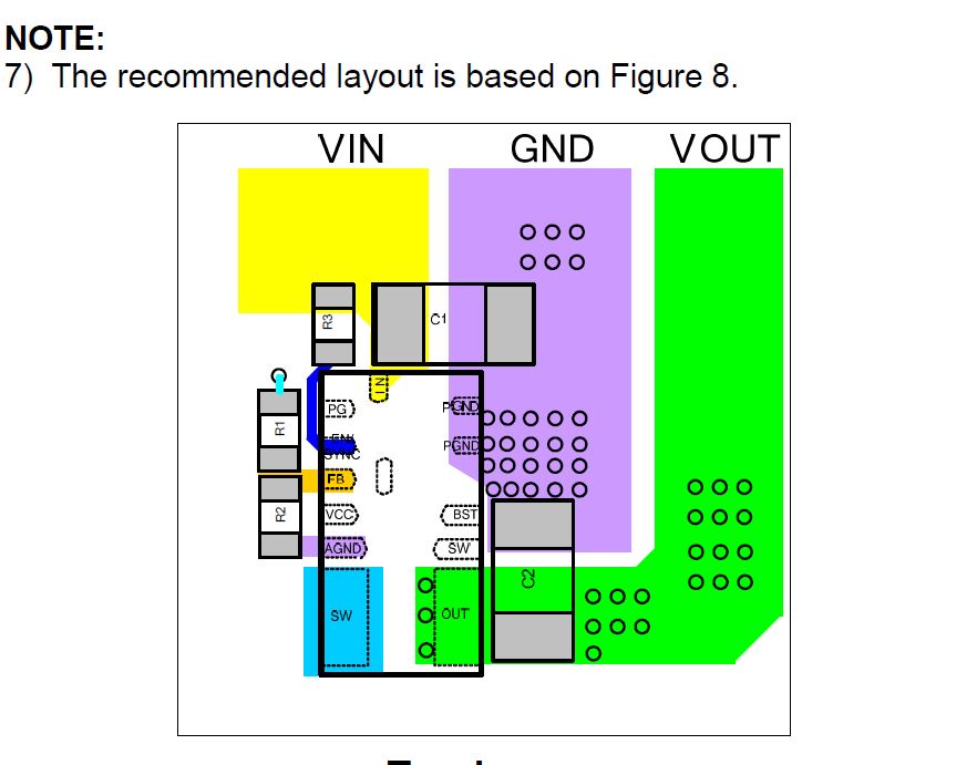
Page 16 has example PCB and text.
From datasheet “AGND is connected to PGND internally. There is no need to add external connections to PGND”
If AGND is not connected on PCB and no way for big currents from external world (all strong current flows thru PGND)
As I understand, you described situation when only AGND is connected externally and PGND is not connected at all .
< Page 16 has example PCB and text.
There is no VIA on the CS/TOP for AGND, only divider of FB connected.
Please point to the text about AGND
Sorry for my misunderstanding.
Question- Should I connect AGND to DGND in layout if DGND have solid connection to common GND?
Please, your final answer?
Hi mikhaili,
Thanks for your question.
You do not need to connect AGND and PGND externally since the datasheet states “AGND is connected to PGND internally”.
For best results, I would not recommend connecting the two externally since AGND and PGND are already connected in a way to reduce signal interference from each other.
Be careful to follow the PCB guidelines for PGND on page 16 of the datasheet.
Thanks,
Cindy
Thank you for your answer, my guess was as you recommend.
Is it mined than layout of EVM3515-QV-02A is not best variant ( it have external connection to AGND )?
Mikhail
Hi,
Are you sure PGND is connected to AGND externally on the EVB? Can you point out where you see that?
Cindy
Yes please,
EVM3515-QV-02A datasheet
- Page2 , schematic-pin5 connected to GND
- Page5, Fig1-Top
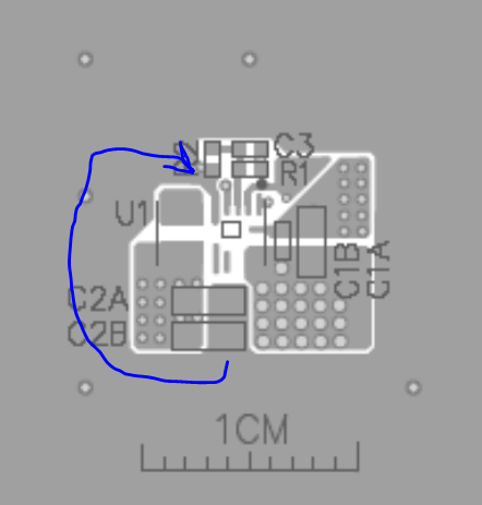
Mikhail
Hi Mikhail,
Thanks for providing that picture. Yes, I can see that they did connect AGND and PGND on the EVB. I’ll need to confirm with the PL why they did this.
However, based off the MPM3515 datasheet layout recommendation, I can only advise to not connect the two grounds externally on the PCB. The FB network is connected to AGND because it has a quiet reference point. Connecting PGND and AGND together would create noise and defeat this purpose, hence why the DS doesn’t recommend connecting the two GND’s externally.
Please refer to the layout recommendation provided on page 16 of the [datasheet].(https://www.monolithicpower.com/en/documentview/productdocument/index/version/2/document_type/Datasheet/lang/en/sku/MPM3515GQV-Z/document_id/2120/):
Thanks,
Cindy
Hi Mikhail,
So disregard what I stated above. Received some clarification.
Connecting AGND and PGND externally will not make a difference on this part. The datasheet is just declaring that you do not have to connect the two GND’s together since it is connected internally.
It is up to you whether you want to connect the two on your PCB.
Anyways, hope that clears things up!
Thanks,
Cindy