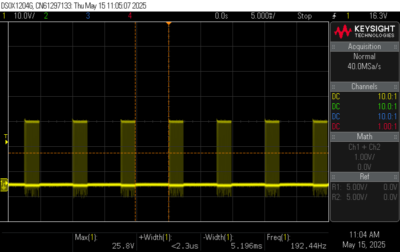
I’ve built a buck circuit with MP9943 and right now upon testing with a electronics load I’ve found a very strange behavior that under CC mode the circuit works perfectly fine but under CW mode the circuit will when into unknown protection mode or some sort of failed to regulate by shorting itself but not fully shorted, and the switching waveform is short bursting. This will only happened when the load is connected first and power up. If I power up the circuit first then connect the load it would not have this problem. This issue also exists when an actual load is connected. And it brokes a few of the MP9943 chips. However, another MP9943 buck circuit within the same pcb board but with 5V output would not have this issue. Furthermore, some I believed broken MP9943 chips I’ve tried also experience a slightly different behavior, the switching waveform is completely messed up rather than a typical short burst. And the problem on exists when input voltage is above 24V, anything lower than 24V is seem to be fine. This is very confusing.
For all wattages, what load conditions did you end up running? I have a feeling that there may be some input current issues. Perhaps this is a symptom of some input conditions?
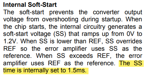
For all wattages, was the load connected first and then powered up? If you want to have the case in which the IC to power up and then have the load supplied would be to adjust the soft start time in order to have this adjusted. In the case this is a main load condition for your application, then this would be understood.
On the subject of input conditions as I initially mentioned, if possible, ensure the power supply is supplying a sufficient enough current or could be varying switch current between 5V and 9V at the output. Not doing so could induce spikes that can potentially damage the IC. Switch nodes here should be observed at these outputs to compare and perhaps isolate the issue. Additionally, this may correlate to the damage that you observed from what you have described.
Let me know if you have tried what I have said and check the input and switch characteristics at these voltages and methods on corrective current measurements within threshold.
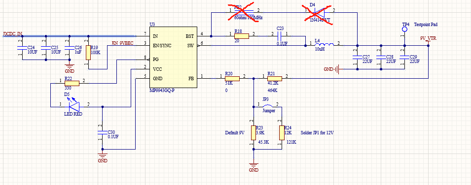
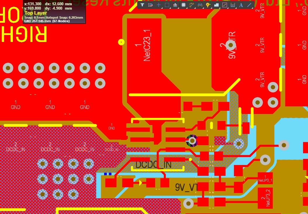
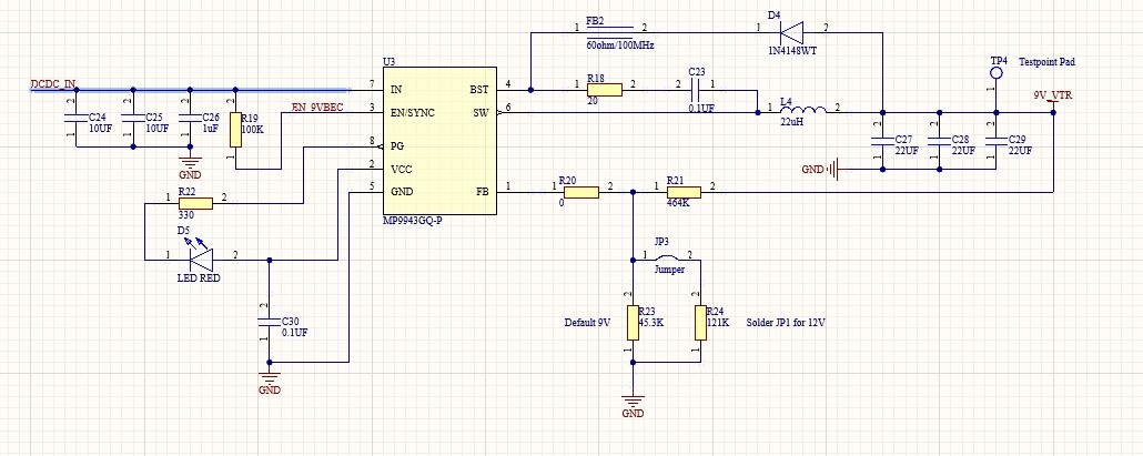
I ask all of these questions because upon reviewing your schematic, I see no outstanding issues. If you happen to have a layout to show as well, which depending on how the trace widths, switch node placement, and certain component replacements, this may also have the potential to influence spikes as well.
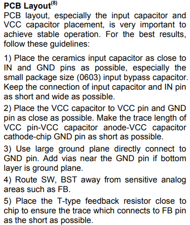
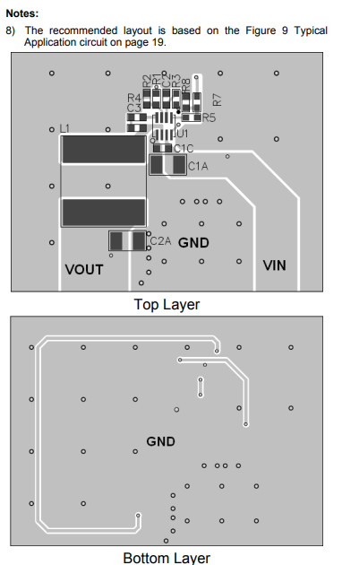
Here are the PCB Layout Guidelines as shown in the bottom of the datasheet:
Q1: I ended up using 1-10W settings on the electronics load.
Q2: Yes, the load would always connected first. Or leave it connected after power off. (In real-life application), does MP9943 have adjustable soft start?
Q3: I’m using a Programmable DC Power supply capable of up to 100W. so the supply current shouldn’t be a problem.
Also, it seems the layout that you provided more or less aligns with the suggested layout that I had provided. Let me know if there have been any design updates since we last spoke.
The values are adjusted based on the MPS provided online DCDC Designer tool.
But unfortunately, this unstable problem is still exist in the production version of the board. The customer is reporting around 1% of the board is having this issue. Not so acceptible to be honest.
I used electronics load to test the problematic unit, it lost regulation in CW mode in the range of 2-6W(9V output), and accompanies with audible noise of the regulator(maybe from the inductor). And interestingly, it works fine for loads over 6W (I tested up to 13W, totally normal, no issue). This is so weird.
It looks like this post was buried, apologies for the delayed response and I hope it isn’t too late here.
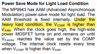
Having troubled regulation between 2-6W accompanied by audible noise makes me think there are unstable behavior between the transition between AAM light load conditions to heavy load conditions or minimum load requirements.
If you still want to explore methods in debugging this issue still:
Try to force the heavy load conditions at 2-6W and see if this instability in regulation disappears. This is what the MP9943 says about this:
Increase the minimum load by adding a resistor load (perhaps 1-2kOhms) across Vout to keep it above the transition threshold in the case the above strategy isn’t as accessible as a viable solution for you.
Check the loop stability by measuring the phase margin between 0.3A - 0.7A. At low currents, the phase margin perhaps shrinks leading to oscillations in the output.
On the subject of audible oscillations, perhaps try swapping the inductor for a higher inductance value. The inductor chosen may be optimal for higher loads but has too low inductance, the ripple current at low loads could be proportionally huge, therefore increasing output voltage ripple. This would also help you optimize on required output capacitance.
I hope these solution paths provide some insight. And I hope this wasn’t seen too late.