We are testing the 100V input, current mode, synchronous step-down controller evaluation board (EVL9929-QW-00A).The output of the evaluation board is 12V/8A.
If there are any possibilities to increase the output up to 12V/40A?
The input voltage range is 16V to 96V.
We have already tested the evaluation board (EVL9929-QW-00A).
In lower input voltage, the converter is working fine. To increase the input voltage >76V, the switching mosfet temperature also increased.
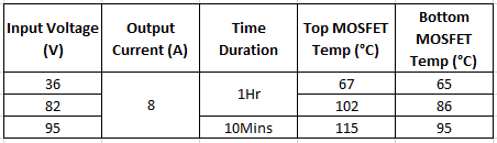
The test results are mentioned below.
Higher input voltage, the switching mosfet temperature reaches >115°C at 10 min duration for 8A output load.
Changing the switching mosfet and inductor to maintain the mosfet temperature <100°C for 40A output load. It is possible?
What is getting you there is switching loss. I would double the value of the inductor and halve the operating frequency and see the effect on temperature rise. Getting 40A in a single phase is going to be ugly, much better to interleave two 20A stages. Go get another demo board and see if you can interleave them and your solution is at 16A already blow some air put a small heat sink on the FETS get a bunch more.
Understanding your point. The 40A output is converted into two 20A. It is ok.
Oberservation in evaluation board (EVL9929-QW-00A):
At a higher input voltage (>70V), mosfet temperature reaches >115°C at 10 min duration for 8A output load.
To increase the output load from 8A to 20A, at a higher input voltage, what is the mosfet temperature?
How to hendle the mosfet temperature at a higher input voltage?
I would find lower rds on FETS and try to find ones with relatively low gate charge for their rds on Infineon makes some nice ones. In any case bigger FETS switch slower which is why you also go to a lower switching frequency to avoid switching loss getting out of control. The other trick is to use heat sinks and or fans, to dissipate the heat better. You are looking for 3X the power of the demo board, this isn’t going to be achieved by changing a few resistors.
Well it should be in the datasheet, now that I have read the datasheet, I don’t see it.
Generally with parts with a gm amp you can just connect the comp pin and the FB pin of both converters together, the final point is configuring one converter to be at 180 degrees with respect to the other. In this case again they should have a sch in the datasheet, but I don’t see one. It seems you connect the synco ( sync out pin) of the master converter to the EN/Sync pin of the slave converter and that will run the slave conerter 180 out of phase with the master.
You really need to get a second demo and hook them up to see if this works, or perhaps some ap support. they push mps-now for the more involved questitons.