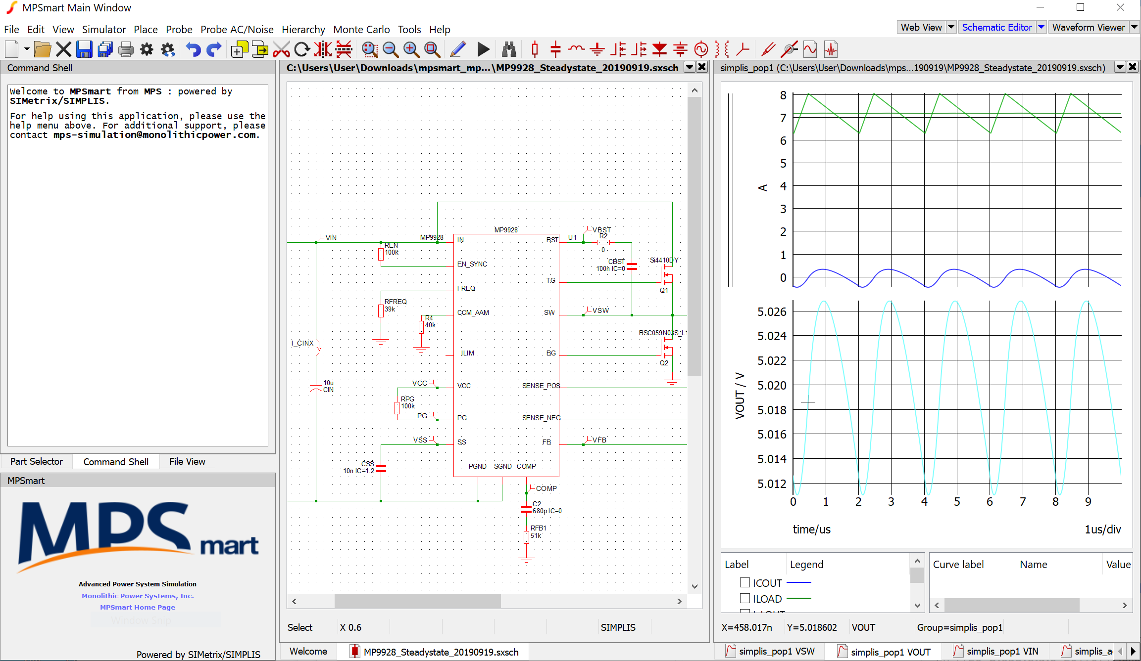
I want to set the output to 12V. I change RFT to 169k as suggested in Table 1 of the datasheet, and press run.
The simulation fails with the error:
The periodic operating point (POP) analysis has failed to converge. AC analysis will not be performed.
Additionally there are warnings reported:
Periodic Operating-Pt Analysis:
Unable to find a periodic operating point after 20 attempts. Check your input file for errors. A change in the initial condition may be necessary.
The voltages of the following capacitors and the currents of the following inductors are the leading contributing factors to the non-convergence of the POP analysis. Inspecting these voltages/currents from the “POP progress output” may show the clues to the non-convergence.
X$LOUT.L1, X$COUTX.C1, X$COUTY.C1, CBST, CSS
Can you help me understand what is going wrong? Any assistance would be greatly appreciated. Thanks.
One thing I noticed is that if I leave the model as-is (still set at 5V out) but change the value of R1 (the ISENSE resistor), it causes POP to fail. Any idea why this would be the case?
For example, setting R1 = 1mOhm gives the error:
The periodic operating point (POP) analysis has failed to converge. AC analysis will not be performed.
And the warning message printed is:
Periodic Operating-Pt Analysis:
…
The voltages of the following capacitors and the currents of the following inductors are the leading contributing factors to the non-convergence of the POP analysis. Inspecting these voltages/currents
from the “POP progress output” may show the clues to the non-convergence.
X$LOUT.L1
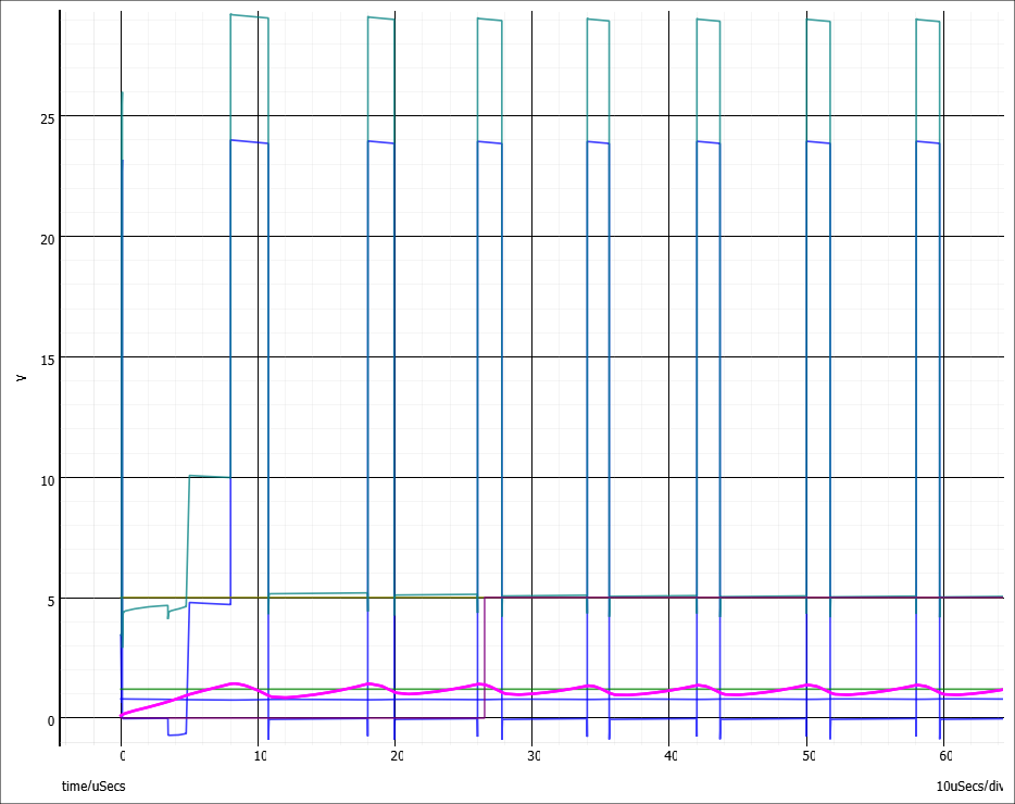
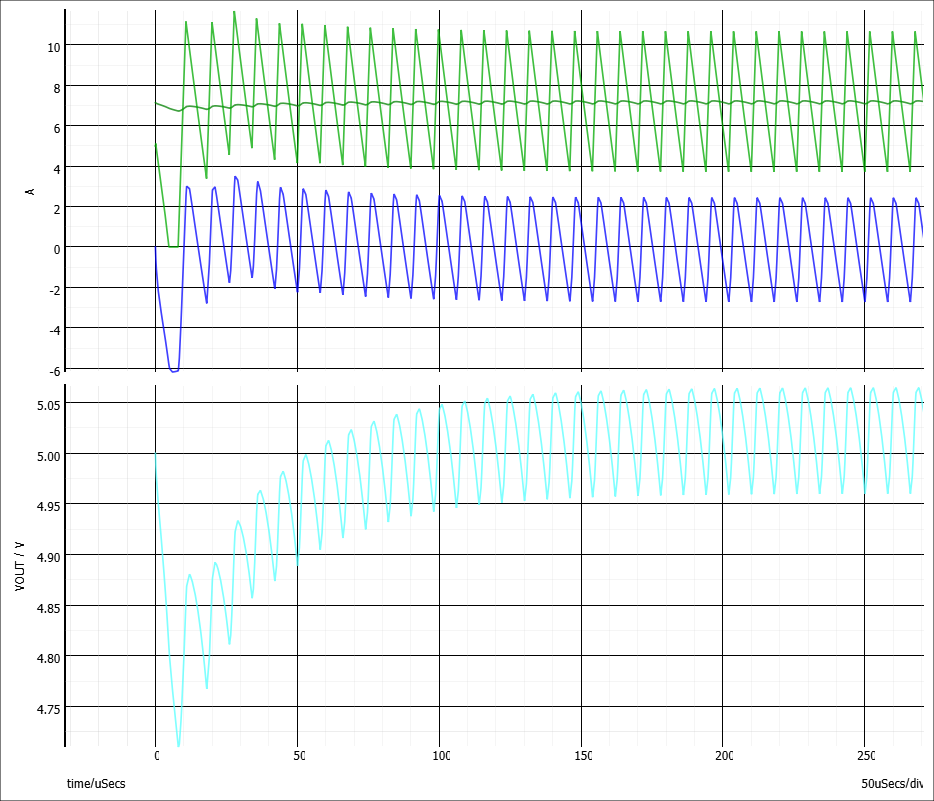
But the transient simulation seems to show steady state …? Unless there is too much ripple on the COMP pin? I’m not sure if that would cause POP to fail. The COMP trace is highlighted below.
I was able to get this working with assistance from Baojuan. Thanks very much for that.
There are a couple considerations:
The current sense resistor needs to be low enough that the device does not hit the current limit.
The model will not find a POP solution if the chip goes into AAM mode. Allowing the CCM_AAM pin to float puts it in forced CCM mode and POP works.
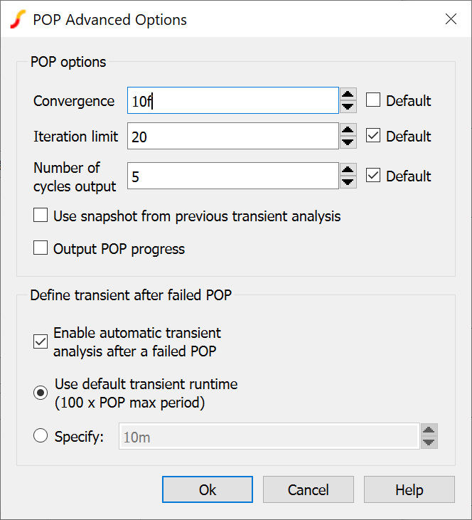
One other thing to consider is that by default POP needs to find a solution within 20 iterations. (Though this value can be changed under Simulator > Choose Analysis > Periodic Operating Point > Advanced).
The initial conditions are specified to be near the operating point so that a solution can be found within 20 iterations. This is why e.g. LOUT is set to an initial current of 5A and the soft start capacitor is already set to 1.2V.
So if Vout, Iout etc. change then those initial conditions may also need to change to allow POP to find the new operating point quickly enough.