Hi,
Sorry, i forgot to add the Vcc capacitor on the simulation schematic i provided, i actually have a 2.2uF ceramic capacitor on this pin. Similarly, i forgot on that schematic the 2.2 ohms resistors on the fet gates which allow tuning of the turn on rate. My 10 ohms resistor between Vcc and Bst was there to limit the current at startup since I have a large value bst capacitor.
I changed the BST capacitor to a 0.1 uF, and I noticed no change. I also tried increasing the gate resistors value and noticed no change.
However, a new thing i did notice is that if I increase the current (around 8 A) the low side on time progressively rises and the issue disappear. It seems that the controller is in DCM on a too high range of current. To sum up :
-
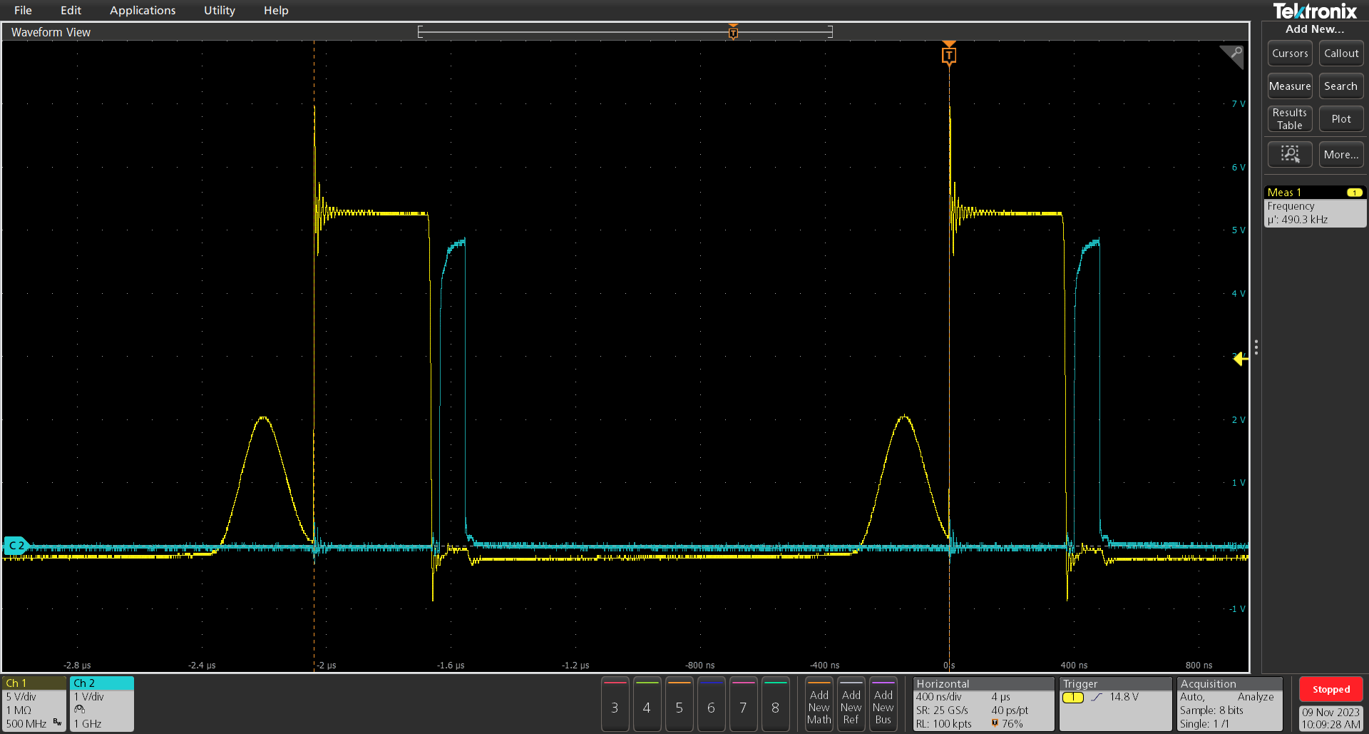
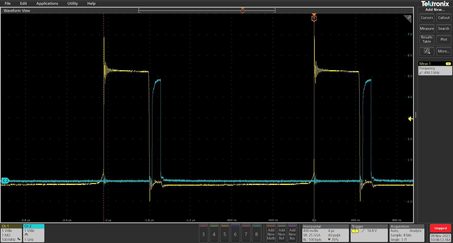
I have DCM from 0 to 2A which is expected considering my ripple of around 4A. The low side control signal is too short however (yellow switch node voltage, blue, low side gate voltage) ;
-
above 2A i am out of DCM but the controller still apply the minimum on time ;
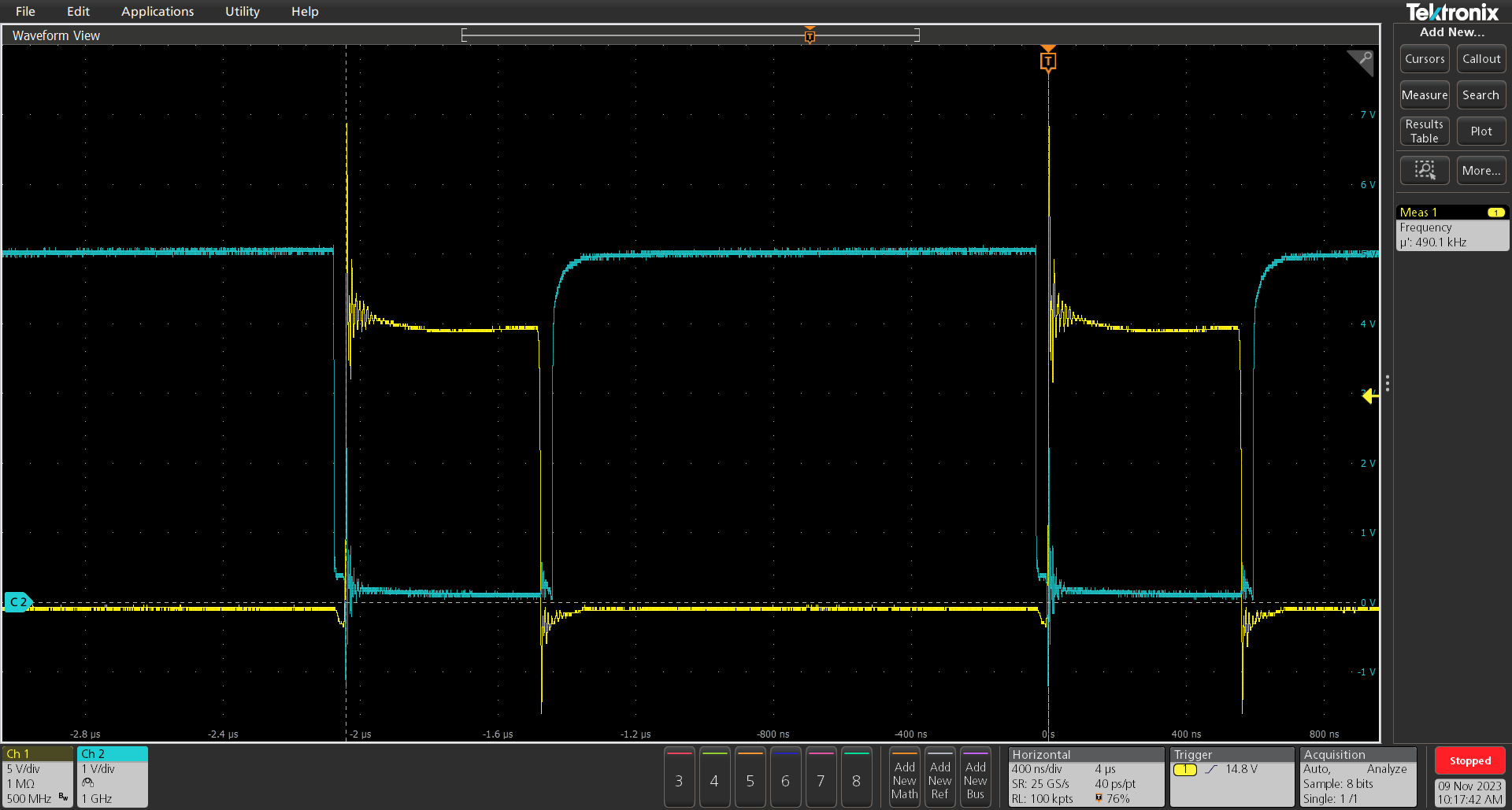
-
at around 8A the controller start to rise the on time until it is properly complementary to the high side.
The two possibles causes i identified are :
- noise on my current sensing which could cause mistriggering of the DCM. It is unclear in the datasheet how the controller controls DCM. It seems to be independent from AAM.
- unadapted compensation network values, but in my opinion it would not only affect the low side. My frequency and high side on time are very stable so is the output voltage.
Additionally, I saw on the forum another topic with a similar issue, although it seems that they have solved the problem on their end : Please check the Mos driver waveform of MP9928
If you see any other possible sources of this failing DCM control or if you have more details on how the MP9928 controls it, I am interested.
Thanks in advance.
Teo Robert