Hello, I am planning to use the MP9488GS buck regulator in a new design as an alternative to another regulator i already tested but i am having some problem: when using the regulator in light load condition (only R4 as load) the output is not regulated and it changes while vin changes
Acually also the VCC is unstable, it looks like the internal supply is always turning off and on
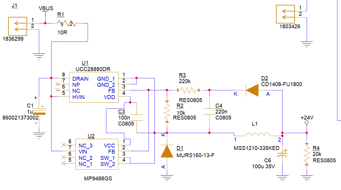
Here attached the schematic
When mounting U2 instead of U1 i use C3=2U2, R3=82k, R4=5k6
Do you see anything wrong in the schematic?
Thanks in advance
Hello Matteo,
I didn’t see an input voltage so note that there may be a min dropout with the 24V output, so make sure Vin is high enough to support the Vout=24V. Next, R4 may need to decrease to support the min dummy load which is 3mA to 5mA which is required for regulation. Also look at adding a feedforward cap to R2, as in the data sheet, pg 18. to stabilize switching, the value there is 470pF but can go down to 330pF for your value of R2.
Best Regards,
Hello,
-VBUS is the input volttage, it ranges from 100 to 300V
-I increased R4 to 5k6, still not working
-I places Capacitors in parallel with R2, i tried values from 100 to 470pF, still not working
The output is around 20-24V but it is unstable and depending both on the load current and the input voltage
Furthermore i can hear a strong acoustic noise in the inductor
Hello Matteo,
The audio noise at the inductor helps here. Try to lower the inductor value to 680uH or lower, same size is OK, the inductor used now is marginal for peak current at 700mA or so, a lower value inductor, same size, can handle higher peak current.
Also its OK to try a larger value for FB cap parallel to R2, up to 2.2nF. Note also there isn’t much advantage to having high feedback resistor values, so R2 and R3 can be reduced, R2=5.1k is good. This allows more current into the FB cap for output regulation. A larger input cap can help also, that is where all the switching current comes from, so at least 2.2uF is needed, the eval board uses 10uF electrolytic. If there is still a regulation problem please take a scope photo of the output and post that. It would help to look at the SW node waveform.
Regards,
Hello James,
I tried to increase the value of the cap in parallel with R2 with no result, also the reduction of the R2 value wasnt effective.
I will try to lower the inductance value, i ordered some inductors that i will try in the next day
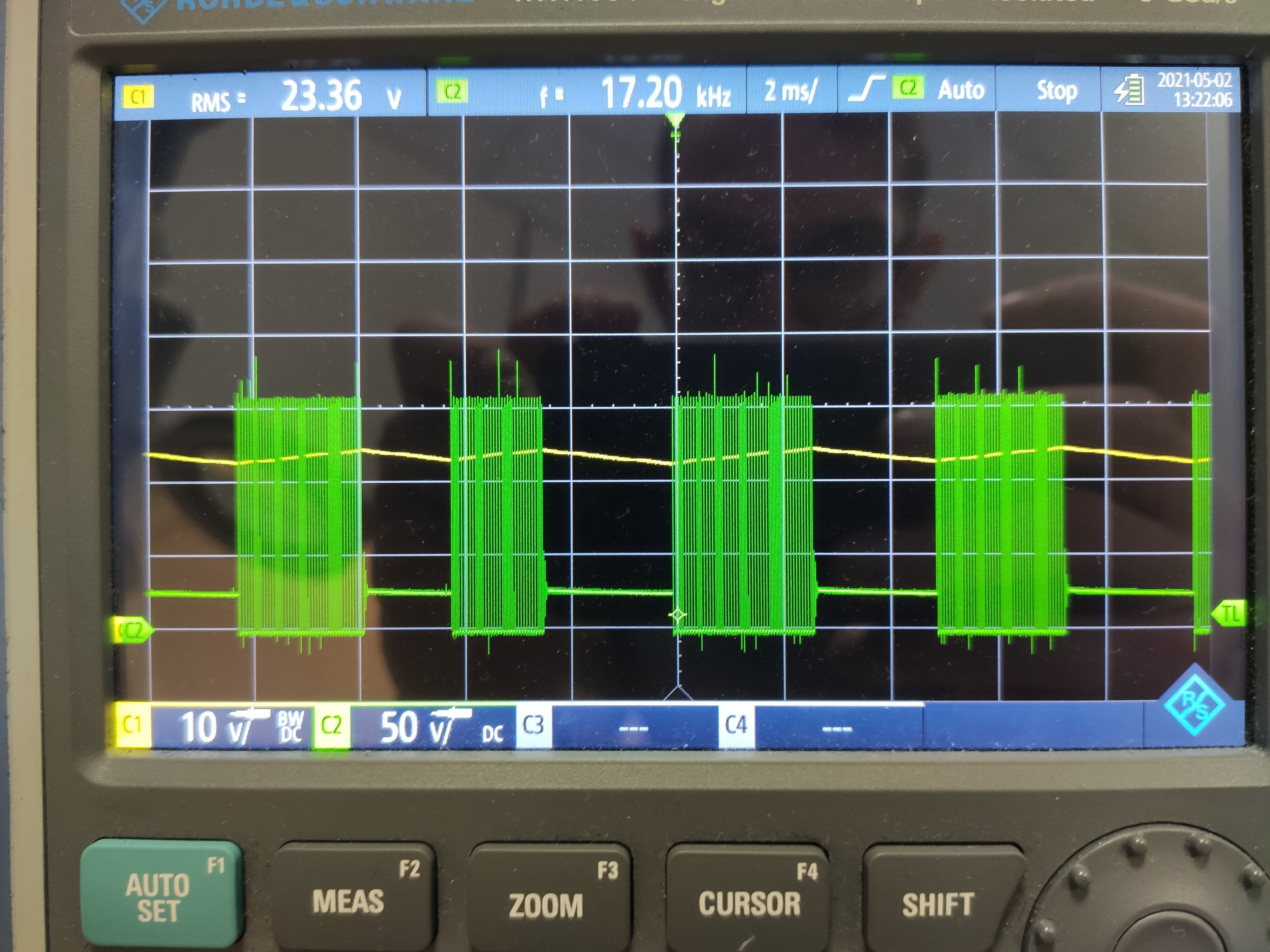
Anyway i looked at the SW waveform with an oscilloscope (CH1 Vout CH2 SW), it looks like the MP9488 periodically tries to regulate the output voltage, stops when it reaches a certain value and start again when it goes below a certain value
Just some guy on the internet but the thing to bear in mind is this is a sampled feedback system. What it looks like to me it the rate of decay of the voltage on the sample cap is very much faster than the rate of decay on the unloaded output. So the IC thinks that Vout is low and chucks another pulse at it. If the preload isn’t enough the vout builds and I suppose eventually some safety kicks off.
Does it behave OK with full load?
I would be increasing the value of the feedback resistors by a bunch like 10X
Another way to think about it is the output load is 80mA with a dummy load of 1.2ma
So we have a 100uf cap being discharged somehwhere between 1.2 and 81.2mA
The sampling cap is 220nF ( about 500X smaller ) and is being discharged with 0.26 mA. This means the voltage on the sampling cap is rarely the same as the voltage on the output cap, and is certainly decaying faster. If you want the same decay as the fully loaded output you would target about 0.16mA of discharge, if you want the same decay as the lightly loaded case ( which I expect is closer to the right answer you would target 2.5uA of discharge. That would push the feedback to 10meg which is a bit high. Any case I would be trying much higher value resistors in the feedback network