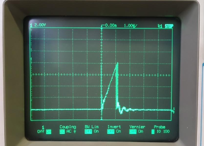
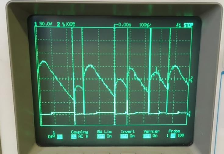
Using pretty much same circuit as page 18 of the rev1.0 MP9488 datasheet, but with resistor values scaled to give 4V output (load ~ 100mA). Inductor is still 1.2mH and input capacitor 10uF. Input voltage is bridge rectified mains (230V ac). The circuit works ok in the sense that it provides the required regulated output voltage but the inductor makes an annoying whistling noise at around 6-7kHz. I tried downsizing the inductor to 560uH but no significant change to noise frequency. Realised that I have perhaps misunderstood steady state operation - the noise I think is more to do with the rate at which the MP9488 bursts current into the inductor when the output voltage has dropped below a certain threshold. Scope shows single pulse SW bursts around 10us wide at every ~120us. Not quite 6-7Khz but near enough I guess. This is more related to the rate at which the output capacitor discharges into the load i.e reaching threshold at which MP9488 decides it needs to dump more current in. I don’t really want to reduce the output capacitance to try and shift up the frequency to less audible range. Any other ideas? (sorry no scope pictures in suitable for yet)
Hi,
We are looking into this request for you, we will get back to you on this.
In the mean time, can you please provide us
- what the input voltage is?
- Possibly Scope captures for Vout, Isw
- Please confirm values on the feedback network
Best Regards,
Nouman
The input voltage is bridge rectified 230Vac so around 320Vdc into a 10uF 450V electrolytic capacitor. With reference to the circuit diagram fig. 9, on p18 of the datasheet: R1=6k8, R2=10k. Output voltage is ~3.8V (so a bit lower than the calculation value of 4.28V). D3,R3 not used since Vo is lower than Vcc. D1,D2 both RFN1L6S fast diodes. To measure Isw a 30ohm resistor is placed in series between C1+ and Vin and voltage across the 30ohm resistor scoped as below. The other scope picture shows the ac voltage on Vout (trace 2) vs Vsw (trace 1).
Hi,
Apologies on the delayed response,
I had to methods of going about it. My considerations would be on the taking a closer look into the layout for inductor, and also possibly lowering output capacitor value slightly. You may use smaller capacitances like 2.2 or 1uF to deviate lower or as increments.
You may also refer to this as another resource:
Audible Power Supply Noise | Article | MPS (monolithicpower.com)
Kind Regards,
Nouman