Hi,
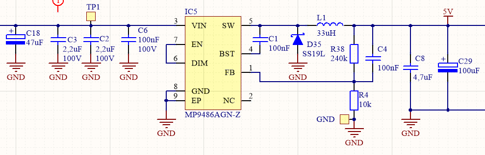
We are using MP9486AGN chip to power our device from 9-95V, with output set to 5V, max 1A. Output capacitor (100uF) is electrolyte capacitor, ESR not defined by datasheet.
What we see is that switcher works well up to 65V. Output is well regulated and stable. But above 65V, 5V changes (with load) from 5V to 5,2 sometimes even 5,5V or more. This is really not what I would expect.
We have made a test with tantalum capacitor (100uF, ESR 160mR) at the output. There is some improvement - output load and line regulation is better compared to electrolyte capacitor, but much worse than below 65V.
Any suggestions what to do? If I have put a resistor in series with C4 (tested with 1k and 4k7), then I face start-up issues described by other users.
Many thanks for your help.
Simon
that’s basically the same circuit as in the data sheets. (and yes ESR is defined - 200 mR by the cap used.) But remember this is a 10:1 input ratio, getting right up there, Your board layout will become more critical as you will be dealing with low on time.
Also note figure on page 6 of the data sheet. See how the regulation diverges. What current are you drawing?? You may need a dummy load resistor (4k7 or even 470R) to keep the supply in check at higher input voltages (resistor and zener?) note at 1ma load, 15% efficient, 10 ma load, 50% efficient, so you don’t waste much.
Hi Simon,
I verified the results of the Line Regulation test for the MP9486, and it should be regulating within +/-0.6%, which it is not in your case. I will need more information to understand your system further:
What type of load are you using and what is the load current? If it’s a constant current load and its drawing 1A continuously, it should regulate normally.
Can you please provide the inductor PN? The peak inductor current cannot exceed the saturation current rating.
Can you please provide the switching frequency you are using?
Please verify the feedback resistors values in your circuit, if they are different than what you have posted here, it will regulate differently.
Feel free to reach out if you have anymore questions.
Thank you,
Eliza
1 Like
Dear speacock and eliza.castillo
It is very hard to measure the current draw from 5V (I need to destroy the board), but I would really doubt that we are in 1mA range, since we power many parts on the board. I will try to measure it, but consumption is definitely not constant since we have LTE module on board.
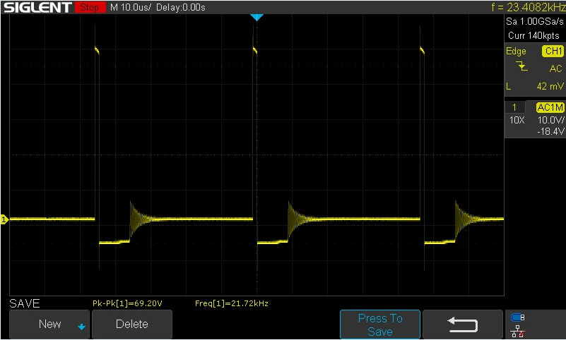
Inductor is: NR8040T330M. As far as I understand I cannot select switching frequency for hysteretic switcher, but frequency changes with load.
This is a typical inductor voltage at like 48V input- frequency around 21kHz.
I see that tantalum cap is the right way to improve output voltage, but it is still not as fixed I would expect.
On the same issue… but not the PSU voltage… Consider putting a 3A (or greater) Ferrite bead in the output of the regulator after the C29 in future designs. I do this for two reasons. 1/ so you can isolate and measure currents. 2/ It helps keep the feedback loop in phase (a phase error in the output loop can cause the voltage to go out of spec)
After a lot of testing I have resolved the issue. First big improvement was made with the selection of right tantalum capacitor. Remaining issue was resolved when I have removed 22uF before DC-DC converter which was supplied from 5V. 22uF cap was like 10mm away of the tantalum one, but ground return path was not routed ideally due to board constraints and obviously, that caused phase error in the output loop. When 22uF cap is removed or when ferrite bead is mounted in between, output voltage is stable.
I cannot stress enough how important the correct GND is… The ground for the PSU should be the output cap. Preferably all the grounds use the top layer so the only vias are by the output cap. It will solve a huge number of issues without them ever becoming an issue. The ferrite bead was from Dr Riddley. Best article on designing a PSU filter I’ve read He really knows his stuff.
I’ve also had it drummed into me by a PSU expert. The return path is everything.
So for people reading this article, consider these things especially the ferrite bead as without it, every capacitor on the board affects the phase of the PSU.
Simon