Hello,
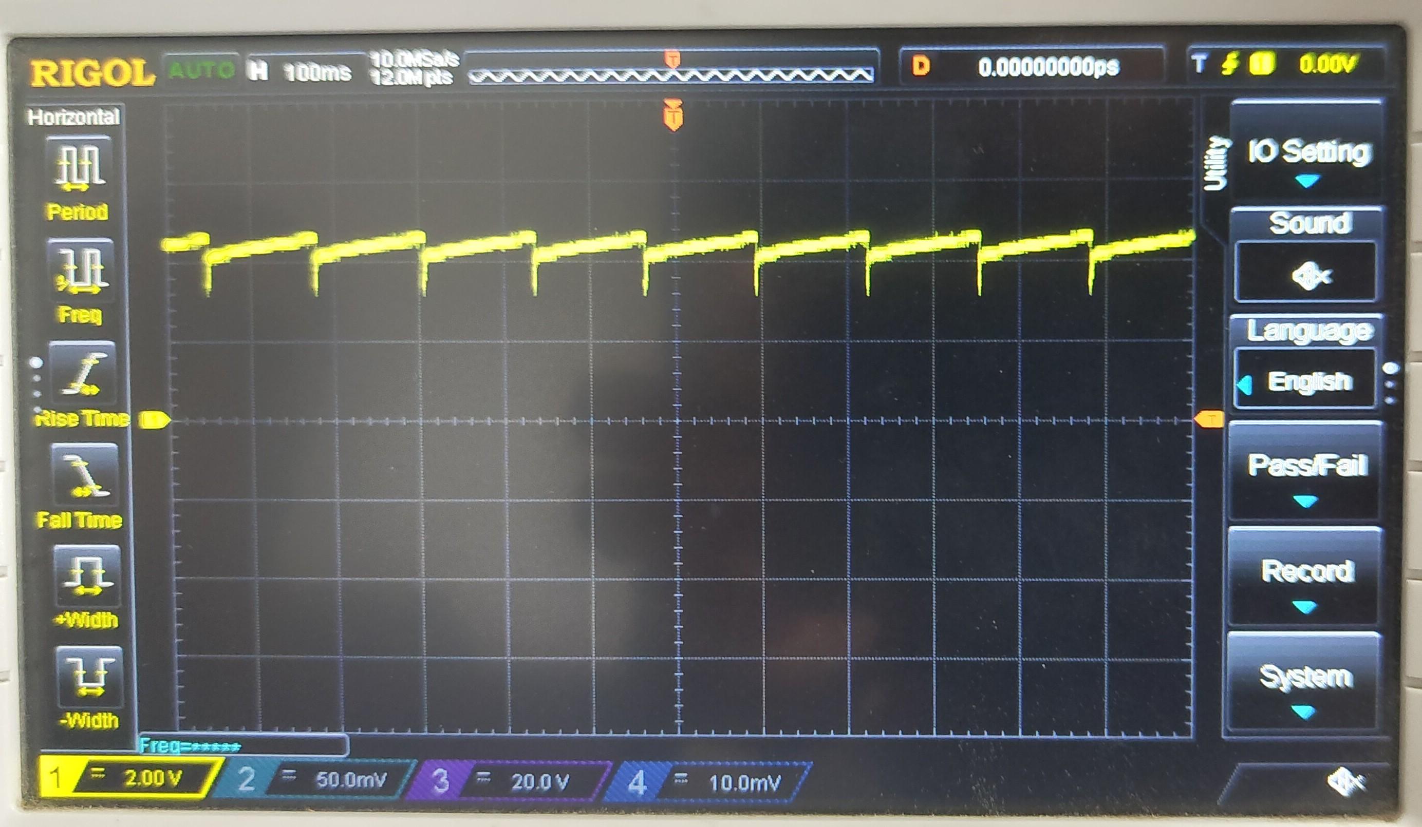
I am back again with another problem with MP9486A. My input voltage is 12V and output voltage is 5V/800mA. Please see the waveform below:
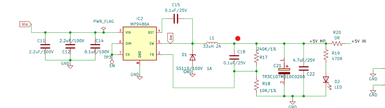
Since we can have only 1 embedded image per post, I will add the schematic as a reply.
It looks like some sort of protection is kicking in and disabling the output. I changed R20 to 0.5Ohm
to act as a limiting resistor and when powered on, everything worked out fine.
The other interesting observation is that when the Vin is changed from 12V to anywhere above 60V, it works as intended. What is going on here? Please let me know if you need any more details.
I see that this IC is not listed on your online DC/DC design tool. Why is that? Does this IC have known issues that you don’t recommend it? Do you guys have an errata for this part?
Please find the schematic:
Hello @abhijith.narayan,
After changing R20 to 0.5 Ohm, Is the part working fine for Vin= 12 V to 60 V? If so, then what’s the output current and how does the switch node voltage waveform look like? Can you share your layout as well?
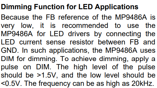
I also want to highlight the dimming function of the part. The DS says the following
To answer your question about the online DC/DC design tool, we have design resources for most of our parts but for parts not listed, we highly recommend using the eval board or follow the layout design guidelines mentioned in the DS.
Best,
Saquib
Hello,
We rectified the problem in the meantime. When the switching inductor L1 was changed from 33uH to 68uH, we noticed that there was a “delay” in the startup. When the bench supply is turned on to power Vin, we noticed that the IC doesn’t draw current from the supply for 1/2 seconds and then starts to draw current and everything works normally.
By adding an additional 22uF capacitance to the output of IC, the problem of the delayed startup is also fixed.
Can you please revisit the calculation for the output inductor for us?
Thanks,
Abhijith.
Hello @abhijith.narayan,
For operating in low voltage ranges, the part may startup into SCP mode if the load is on during startup and the turn-on threshold of the E-load is below 0.3V. In order to enhance the startup capability, the LC filter capacitor value (C18) should be increased. Equation (2) on page 13 shows the relationship of inductance with other circuit parameters.
Let me know if you have any questions.
Best,
Saquib