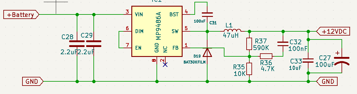
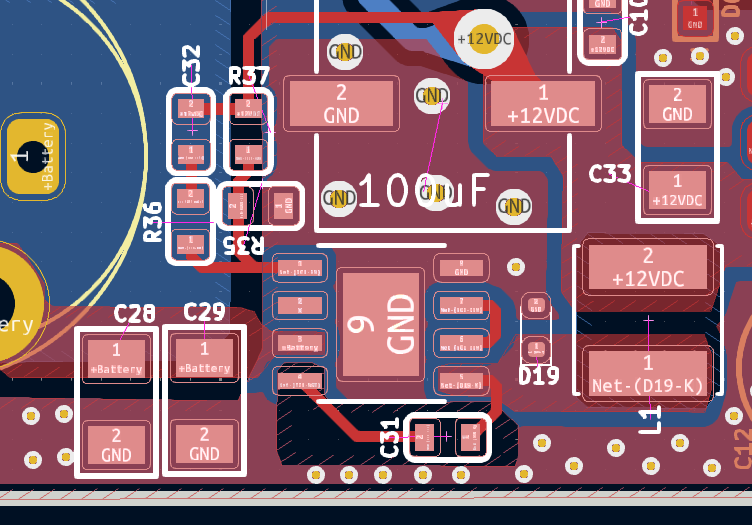
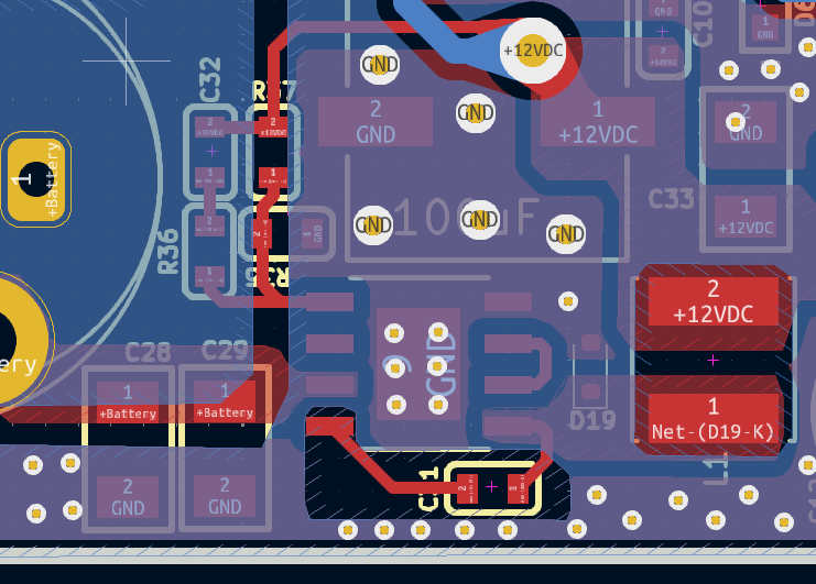
I’m currently designing a BLDC motor controller PCB for a 1 kW application, with a maximum input voltage of 100V. I need a 12V, 1A output, and based on these requirements, I’ve created the schematic and PCB layout.
Could you please take a moment to review the design and let me know if there’s anything I might be doing wrong, anything missing, or areas where improvements can be made? Your feedback would be greatly appreciated!
Additionally, I have a couple of questions:
While calculating the inductor value, what switching frequency (Fsw) should I consider for optimal performance?
If I want to change the output current rating in the future, which components would I need to adjust or replace?
Attached are the schematic and layout files for your reference.
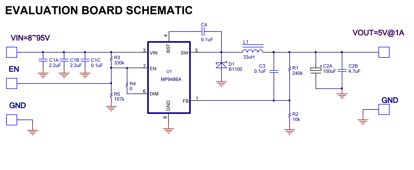
Apologies for missing other questions you had. For calculating the inductor value, there isn’t a fixed frequency value to consider but please make sure the switching frequency is under 1Mhz as mentioned in the datasheet. The inductor current should be continuous in each switching period to avoid hitting the current limit since the required output current is low.
The output current plays a vital role in selecting the inductor, output and input capacitors. If changing the output current rating, these components would require some adjustments based on the formulae mentioned in the datasheet.