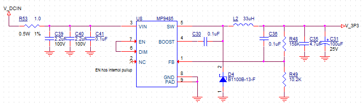
Hi, I build a circuit with this buck converter to convert 10-95v to 5vdc. The load varies between 5 and 50mA. At first I had not enough capacitance on the converter, so the output went out of hand at for example 40v. The ripple increased over 100mV and the effective output voltage increased as well.
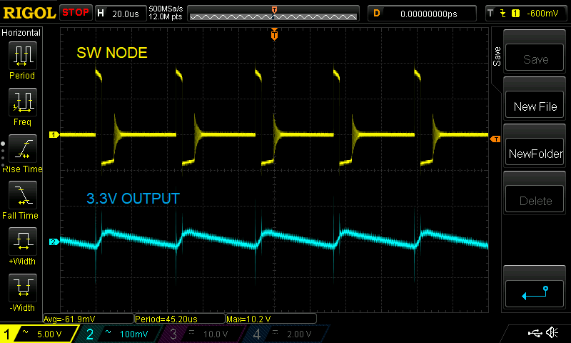
I noticed that when increasing the output capacitance, the switching frequency dropped. I ended up using a 100uF capacitor as advised. With my light load (5mA) the frequency stays around 11khz wich is pretty low. I started trying out other inductors, but came back to the 33uH as advised. I placed it by accident the wrong way around (the dot to the output, while it should be at the switching input) and to my surprise the frequency increased to 33khz. I can reproduce it with multiple boards. Also the placement of my capacitors is critical.
My question: how to increase the switching frequency while keeping the output ripple low enough?
1 Like
Hi Robert,
Thank you for utilizing the MPS Technical Forum.
The part you are working with is a traditional buck with a HS switch and a fast Schottky Diode. The inductor converts the switching voltage to a smooth current on the output. The output capacitors help with lowering the ripple.
For lowering ripple:
I recommend adding 2 additional ceramic capacitors on the output rail in parallel along the output cap. Typically, ceramic caps are smaller in value than the polarized output cap. You can can try 4.7uF along with 100uF. All 3 caps in parallel.
For increasing SW frequency:
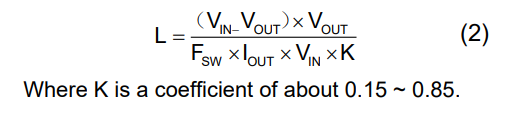
You can utilize the inductor equation listed in the component selection portion of datasheet.
Regards,
Nouman
Let me continue this instead of starting a new thread. I’m trying to do 60V in and 3.3V out, maybe 25-50mA, similar to above. I’m using 12V in for the moment for testing. The switching frequency is only about 20kHz, with massive 100mV ripple. The formula above is straight from the datasheet, and in no way indicates the 20kHz I’m getting, or anything in the low kHz region. I understand this is probably related to low current draw. but there’s not really helpful info in the datasheet to adjust for this. The formula indicates switching frequency should be in the high hundreds of kHz up to megahertzes. Under light load the formula says the frequency should be even higher. How do I keep this out of the 20kHz range so that I can get the ripple back down in reason.
Thanks.
This is a cute circuit but hard to analyze. You could maybe simulate it.
Looking at the published switching thresholds the ripple should be ±7.5% not accounting for time delays and overshoots. I presume it isn’t that bad. I would toy with the idea of increasing the ESR of the output cap so the increasing rising current of the inductor works against the ESR to prematurely trip the feedback comparator. Something in the region of 30mohm at a guess. Fiddle with the feedforward cap as well.