In our actual use, the measured efficiency of this chip is very different from the datasheet. The above figure 1 is the schematic diagram. Compared with the datasheet, the main difference is the DCR of the inductor, but the actual effect of the DCR is compared. The efficiency impact is generally 2-3 Points.
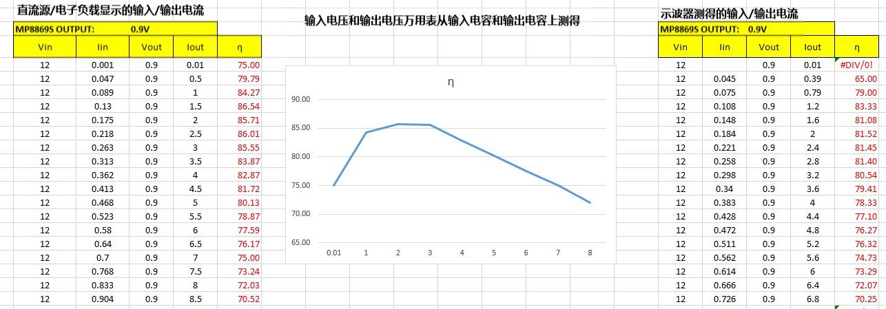
The actual test environment is as shown in Figure 2 above. Therefore, the input is connected to a DC source and the output is connected to an electronic load. The figure shows the measured efficiency of 82.87%. The efficiency of the datasheet 1V output Figure 3 shows that the efficiency at this point is about 91.5%, which is quite different.
Please help analyze why there is such a big difference. Figure 4 above is a set of measured efficiency graphs.
In addition to the displayed filter capacitors, there are several 22uF+1uF capacitors on the load side (the load is an ASIC chip, which has been removed during the test).
you need to Kelvin sense Vin and Vout direct on the board at the Vin and Vout decoupling capacitors. At those small voltages it makes a big difference.
the XAL7020 has 17.6mOhm DCR at room temp. If I add the for 0.9V Vout dominant bottom IC RDSon of 4.5mOhm at room temp, I get 22.1 mOhm DC resistance at room for the dominant power path. That alone will limit the Efficiency to 87% @6A without any other DC and AC losses. Copper resistance rises with about 0.4%/K. So your measurement seem to be in the ballpark. To get an idea you can measure the PCB DC drops with a multimeter in the mV range. Replace the inductor for test purposes with one in the low single digit mOhm range. Check the SW node with a 10:1 probe that your switching frequency is what you expect.
The efficiency vs. Output Current of MP8869S between datasheet and measured by us is very different
Our following set up is different with datasheet:
The inductor DCR is 19 mohm DCR VS datasheet 2.1 mohm.
Output voltage is 0.9V VS datasheet 1V.
Except the output capacitors, we have some 22uF and 1uF capacitors remained on our board.
We use a DC supply connecting to the input of the regulator, and cutoff the other connection of 12V on the board. We connect an electronic load to the output and removed the other load.
We got the current value from the electronic load. We got the input/output voltage value through a multimeter on the input/output capacitors.
Refer to the datasheet, for VOUT=1V, IOUT=4A, the efficiency is about 92.5%. But we only got 82.87% in our testing.
Can you help us analyze why the results are so different?
The inductor DCR is the first thing that stands out to me, the power dissipation in the inductor itself will be significantly higher due to the 19 mohm DCR. Given the high DCR, I think your measured efficiency is around where I would expect.
Thank you very much!
The value of the inductor with low DCR here is only 0.47uH. I used this inductor to replace the original inductor and retested the efficiency, and it did improve significantly. The datasheet requires 1.5uH inductor, if I changed to 0.47uH, in addition to the larger output ripple, is there any other impact?