![image|375x500]
(upload://fzfrJTKFhMzpOsct2PMNGEQASqX.jpeg)
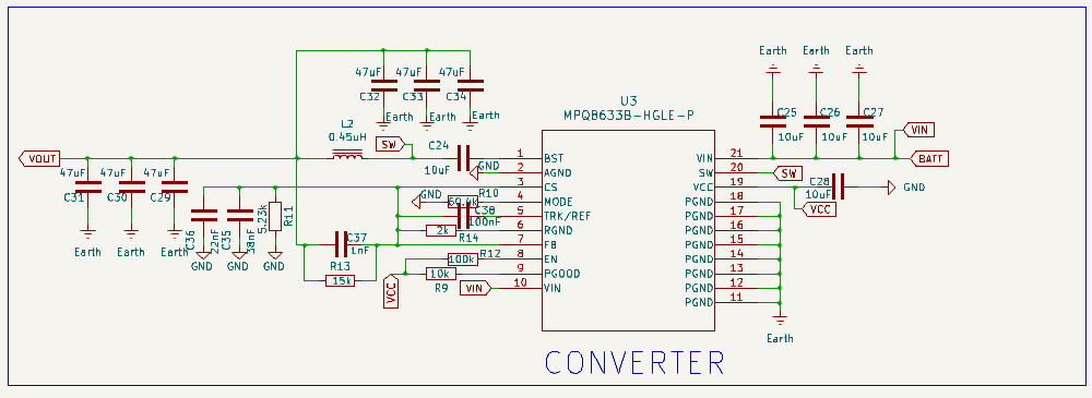
I am designing a buck converter with 12-15v input to 5v input. How to set 5v as output.
Here the voltage can be set using the two resistance but what is Vref how do we determine the Vref
I also read that Vfb must be 0.6v but how do we fix that
What is it required to get the desire voltage
Your questions are scary. I would suggest a demo board as an aide to educating yourself.
The FB pin senses the output voltage via a resistive divider. the circuit regulates the output voltage in such a way that the FB is 0.6V. So the challenge is to dimension the output to FB voltage divider such that when the FB is 0.6V the output must be 5V
If you choose to modify a demo board you should check that the output capacitors are also rated for 5V or higher
I am really sorry to have scared you with my questions.
Thank you for your response.
So according to what you have said and what is written on equation 4 of the datasheet, Vfb and Vref are the same. And the controller tries to keep the voltage at Ref pin FB the same by switching the FETs to keep the desired output voltage(set by the decoder).
So I can just use a voltage divider arrangements with two resistance such that the voltage at Vout is 5v and Vfb is 0.6v.
Please correct me if there is any problem in my understanding.
I will be uploading the design along with the calculations once I have completed, please help me verify it before I move on to fabrication.
Thank you so much.
Hello @mohammedsohailsheikh,
Thanks for reaching out on the MPS Forum. I see you’re asking about setting the output voltage setting on the MP8794.
You’re understanding is correct.
I have attached a resource on design considerations for Buck Converters that you may encounter.
Buck Converter Topology Design Guide
Design Steps and Considerations
Feel free to add your schematic in your future replies.
Thank you for your rensponse
Please verify if i am doing it correctly
Hi @mohammedsohailsheikh ,
Yes, the schematic looks correct.