Hi expert,
Have some questions about CS output of Inteli-Phase devices, just take MP86934 as an example.
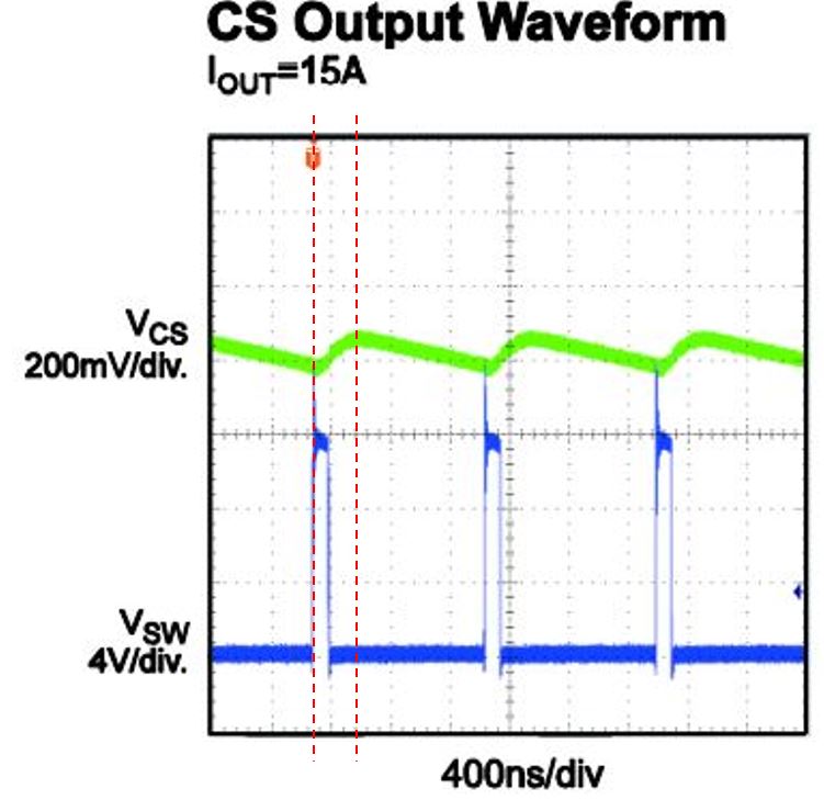
See the emulated output current waveform in this figure, compared with SW waveform, could I know that why these two timings cannot match?(when SW becomes low, current should go downwards)
If the sensing current is not accurate as such poor, with huge delay of turn-off, how could it guarantee feedback performance and loop regulation? I’m afraid of the down slope and valley point accuracy.
This device claims 2MHz switching capability, how to conclude this value? Due to all the internal latency inside(e.g. driving delay, dead time, CS delay)? If possible, I’d like to have a formula, or a figure showing how to calculate.
An observation, the current will be increasing when the SW node is high. So there is still a certain estimation error, but it isn’t as bad as you think. The first red line should be on the falling edge of the SW node voltage, not the rising edge.
Hi Jshannon, thanks for your comments here.
It seems sensing delay might be ~150-200ns.
Anyway, the width of SW high doesn’t equal to current sensing upwards period, that’s the most confusing point.
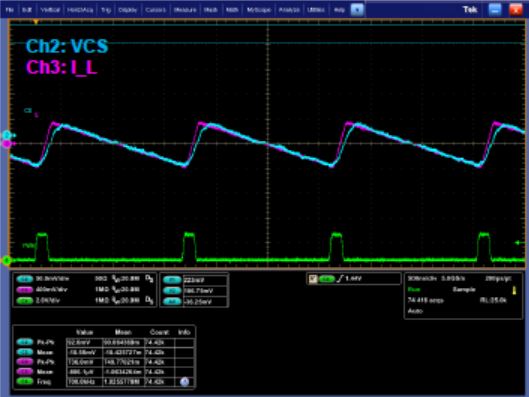
There is some delay, but the current sense signal still tracks the inductor current accurately. Here’s a scope capture of the inductor current, a PWM pulse, and the Vcs signal:
There is a delay of ~250ns in this current sense scheme, so it is good to keep the PWM off time >250ns.