I have received my MP8638 proto boards and none of them work. More specifically:
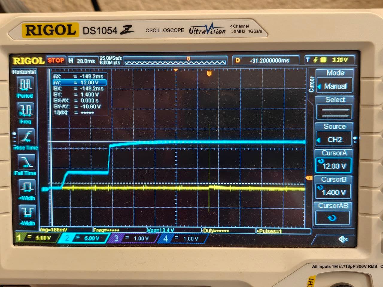
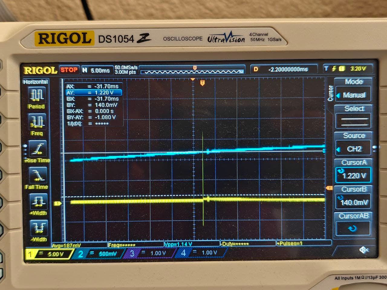
once EN reaches ~1.2V, 3V3 pin goes up,
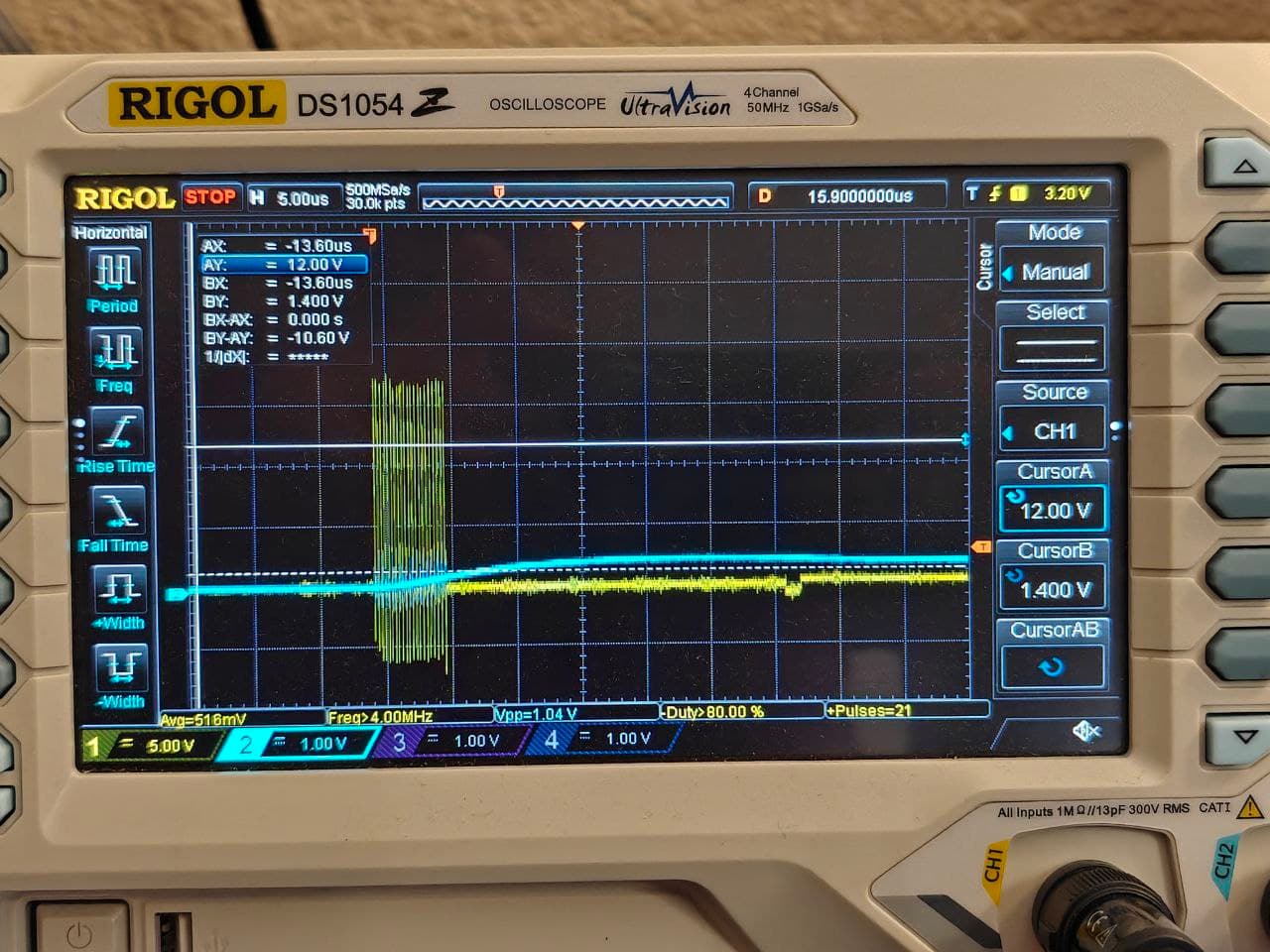
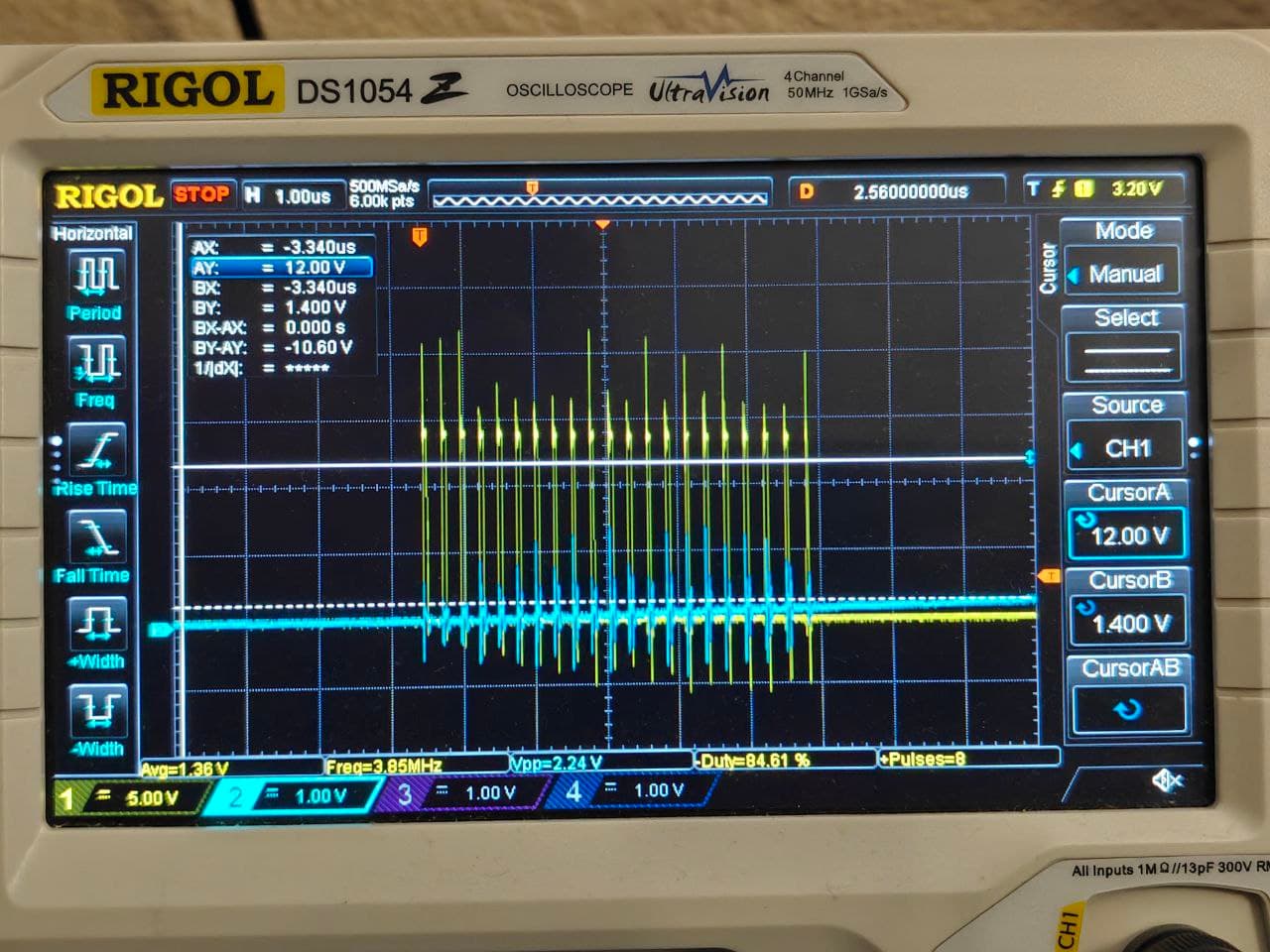
SW produces 21 or 22 12V pulses - 3.8 MHz, 20% duty cycle (the last cycle is sometimes shorter than the earlier ones),
then everything stops,
PGOOD obviously stays low.
My configuration:
Vin = 12 V,
Vout = 5 V,
10 A load limit,
=>3V, 1 MHz,
no load connected, just a few small Cout ceramics,
Since I see the same behavior on all three boards, I assume it’s not a random assembly mistake. I took off and measured all passives, they are correct. I resoldered the MP8638 itself, just to be sure. I also removed the load limit resistor. I verified that there are no unexpected shorts.
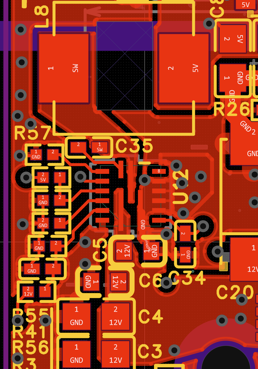
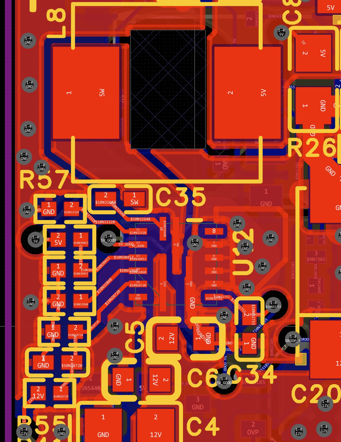
(FB trace not visible, but it is connected. Experimenting, I have cut it and made a separate FB connection with a short wire. Did not help either).
The MP8638 has proper markings on the packaging. PCBWay was instructed to source it from Mouser, I have no reason to think that I got multiple bad/fake parts.
Do you have any ideas on what else I should check?
Sorry to see that you are facing issues with MP8638 not starting up.
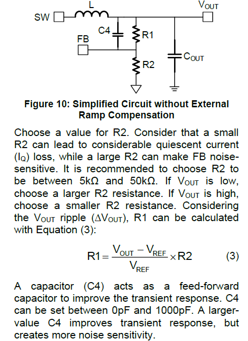
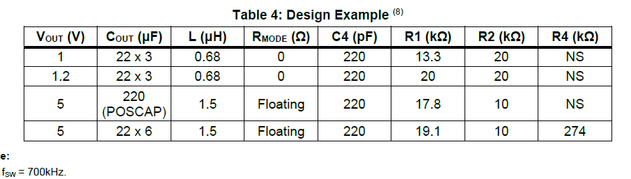
After quickly taking a look at your schematic, R41 value is not as per datasheet considerations, it is lower than what it should be. Also, the feedforward capacitor is not present. Refer to the below screenshot from the datasheet.
I did not install feed-forward cap because a) the recommended range starts from 0pF, which I took to mean “it’s optional”, b) I only have small and slow load transients in my application.
I will replace the FB resistors with larger ones, grab the waveforms, and report back tomorrow. Replacing 4x47uF with 6x22uF output caps is impossible on this PCB - there is not enough room. I can do 4x22uF, if you think it would help.
One more note: 220uF (C12) is a tantalum cap.
In the meantime I have replaced the 1.5uH inductor with a 2.2uH one, which I have used in a previous design. Again, no change in behavior.
Ok, maybe let me change the question - is this even normal for MP8638 to start with these rapid (3.8MHz) SW pulses? In the absence of any eval board it is difficult to know how the buck should behave when everything is ok…
If these pulses are not normal (as I suspect), what could be the reason for the chip generate them?