Hi Team,
I’m working on a custom board using MP8020 and I’ve some doubts.
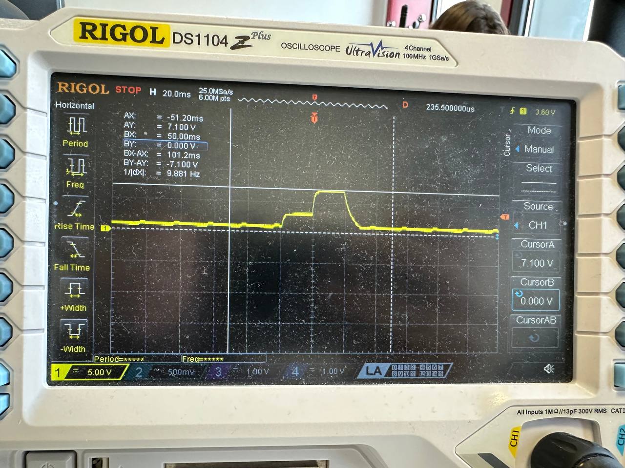
I’m checking with the oscilloscope the PoE negotiation part and as I’ve seen and attached here, the PSE (25W) generates the Detection part sourcing voltage between 2.7V and 10V, about 7V in my case, but the MP8020 does not continue with the negotitation class part (14.5V-20V).
I’ve measure between VDD an GND but I can’t see the 25K of RDET. As datasheet shows a N-MOS enable or disable RDET. As it never appends, the controller part doesn’t work as I spect.
Which are the needs for the MP8020 to close that MOS in the Control Logic part? Because voltage reach the IC and that part should be supply.
What could be the reason why it doesn’t work?
I’ll be waiting your news asap.
Best regards.
Hi jocaca.iot,
If you are ok sharing on a public forum, could you send over your schematic?
I want to check how much input capacitance you have. The IEEE 802.3 standard only allows for 120nF max. If you have more than that, it is possible to fail the detection stage.
The FET for controlling the RDET is controlled internally.
Regards,
Vinh Tran
Hi @vinh.tran,
Thanks for your response.
Finally, I solved the issue. It was in the diode bridge part, which has not correctly design.
After redesgned, it’s been working until now.
I’m playing with PSE Type 4, near 90W, and PD Class 3, 4 and 8. In all of them the negotation and LED indicator part it’s succesful.
However I’ve other kind of issues, in my design I also using an step-down after GATE1 Mosfet to reduce the 57V to 12V and 5V, with a maximun current set of 2.5A for the step-down’s load. I’m using the MP2565DN-LF-P with diferent configurations.
I’ve checked that if a load of more than 2A set in the DCDC output during the negotiation, it ends, but the FET on the GATE1 it’s switching and I don’t have enought power to supply the load part.
Reading the datasheet, I’ve appreciated that the ILIM Resistor could be the reason, so I changed it to a 7K resistor for 1.6A for prevent the OCP, but it’s not enought. The datasheet also anotate that diferents of more than 10V between VSRC and VDD, which is VDS, after 90ms, define if the GATE1 should be open or close.
I’ve no tested all that I’d like it, but looks like I cannot set more than near of 1.6A load, independly of voltage level configurated, in the VSRC part until the negotation ends.
What’s your thoughts?
Kindly,
Jorge
Hi Jorge,
1.6A is the highest that you can set for this part because of 57V PSE output. At 1.6A, this gives 91.2W, which is the max for the .bt standard. If you need at least 2A, it sounds like you will be operating above the .bt max power output.
You should wait till the negotiation phase is done before loading the device. If the device is loaded before negotiation, there will not be proper startup because the part cannot identify the max power the load requires. It can lead to over-power on the PSE.
If you wait till negotiation is done, does the part properly start?
Regards,
Vinh Tran
Hi @vinh.tran ,
Thanks for your quick response.
I really appreciate it.
During my last exposure of the problem, maybe I’ve no been clear enough. My PSE is Type 4, although the power signed in the specification is higher, like until 1.8A. My PD Configuration is able to negotiate in several class, but I’ve fixed it for Class 4, which means 25W aprox.
The board only has PoE connector for supply and deliver 12V and 5V from the DCDC.
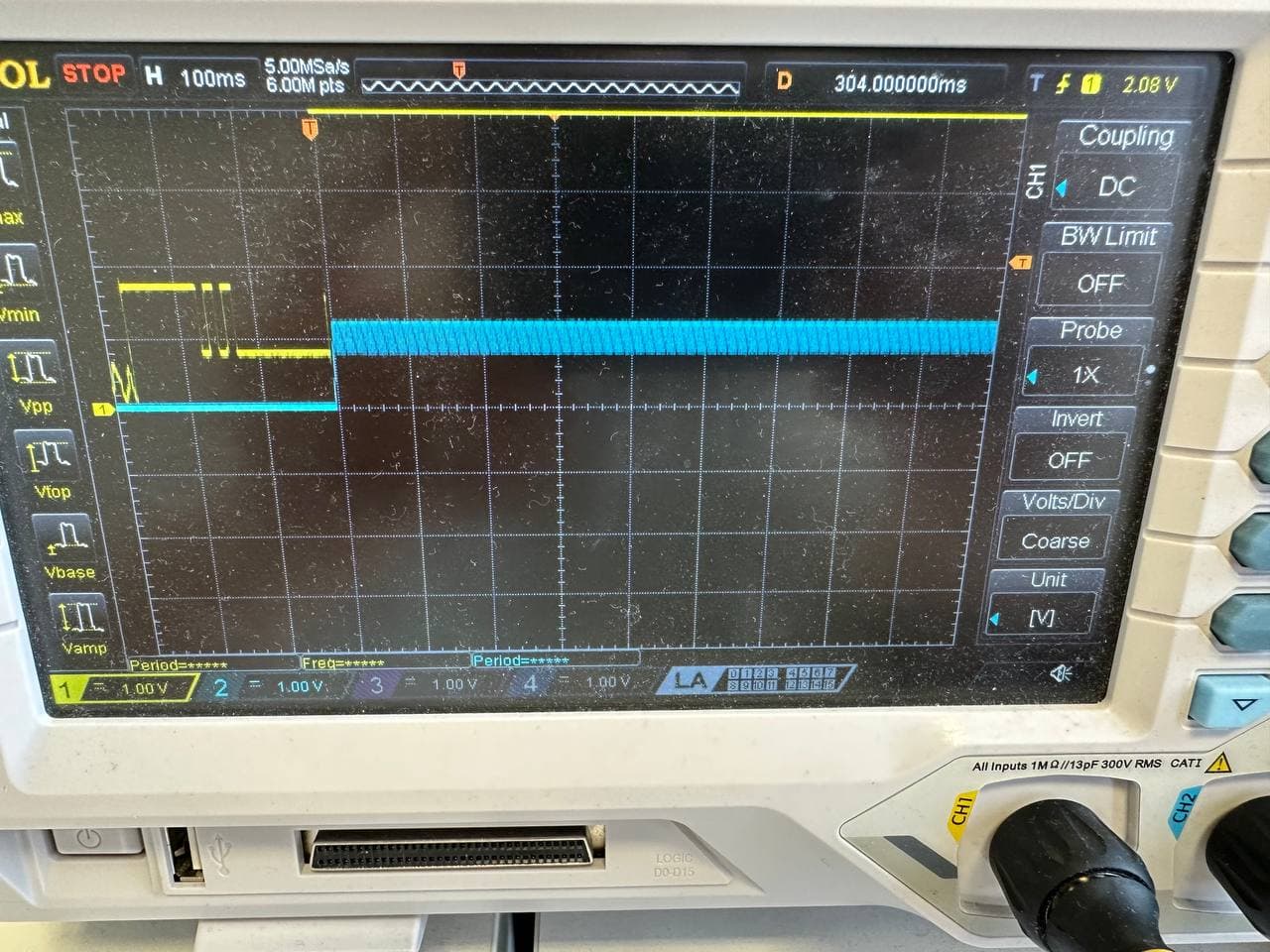
Truthly, it does 2 cycles sequence and BT and TYPx LEDs indicate it, I attach an output from the oscilloscope, where VDD is yellow line and GATE 1 is blue. Important, if I load the step-down later, downstreamming side, it can deliver until 25W and everything works as we should spect.
The slope from yellow to blue is 90ms as the datasheet shows.
If I load the downstreaming before power-up the board, the PD negotiates, but he GATE1 is switching as I show you here, and the steps doesn’t work properly.
I suppose that the OCP is running, but for me it has no sense when the negotation is correct, becouse the PSE and PD know how many power must supply, but GATE1 doesn’t allow them running.
I’ve tried to increase the capacitance in the downstreaming part but doesn’t do any change.
What’s your suggestions?
Thanks in advance.
Kindly,
Jorge.
Hi Jorge,
When you power the downstream device before the fully PD negotiation, do you know how much power it is drawing? If the inrush current limit does not drop below 75% of the limit, it will stay at the inrush current limit of ~240mA. Increasing the capacitance downstream just increases the inrush current required. Can you reduce this capacitance? How much is downstream?
MP8020 has a PG pin. Is it not possible to use this to enable downstream devices once negotiation is done?
Can you check VDD-VSRC? This can show us if there is an OCP.
Is your measurement of VDD correct? The scaling looks to be only 1V, where PSE output is about 57V.
Regards,
Vinh Tran
Hi @vinh.tran ,
Thanks for your response.
En order to clarify the situation, the VDD shows 1V becouse the scope is configured x10, although the oscilloscope could show 10V/div, I’ve prefered to see it in other tiny scale.
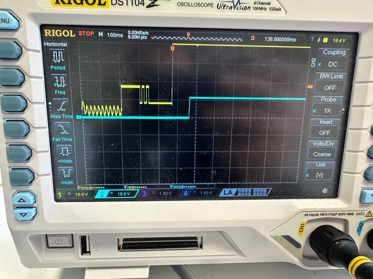
The image from the last commit is from VDD, yellow line, and VSRC, blue line, when it goes to OCP situation, or I think so.
What I’ve been able to see is that GATE1 is swichting constantly, with a period of 100ms aprox. That’s why I think that is going to OCP. Important to mention, it’s that the ILIM Res is 0 Ohms, and RSENSE 18 mOhms.
I’m loading the the downstreaming part with, 20W aprox., less than 25W.
I’m gonna try to connect the PG with the EN of the step-downs, and see what it happends, also I’ll reduce the capacitance in rail from VSRC to VIN of the DCDC, now is loaded with about 30uF as result capacitance.
Let me do the test and update you again.
Many thanks for your support, your ideas are quite interesing.
Kindly regards,
Jorge.
Hi @vinh.tran
Finally I do the test that I promised you.
I removed the capacitors and connected the VSRC directly to DCDC with out any capacitance.
It requieres so much current due to highvoltage and capacitance capcitors demands high current and the PoE OCP doesn’t allow it.
Of course, I enabled the DCDC from the PG pin from the MP8020, doing some tricky wire connection between 0402 resistors, and as you suggested, after 90ms of successful negotiation, the PG goes down, enabling the DCDC after GATE1 leaves the current flow, which is perfect.
I attach the capture for a better understanding, but at the moment it’s solved.
Yellow is VDD and blue is 12V output from the stepdown, so it takes a little bit more since the PG enables it.
Thanks for your comments.
We’re in touch.
Kindly,
Jorge.