Hello,
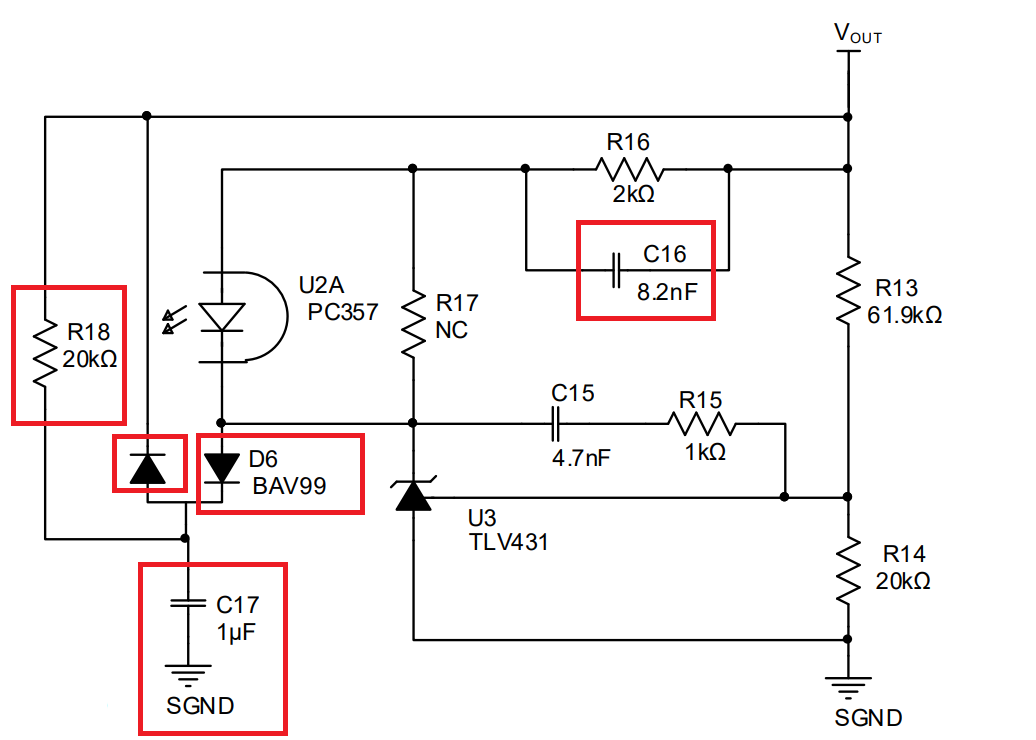
I am not really sure how to adapt the feedback circuit to different output voltages as it includes some parts, I don’t fully understand right now. I’d be happy if someone could explain the purpose of the components I highlighted with red boxes. And do I need to adapt them if I want to have a different output voltage or is it sufficient to change the components included in the Flyback Design Tool | MPS?
Thanks for your help!