Hello,
We have a problem with the prototype boards we developed with the MP8017. Half of the boards have problems starting up under any load.
The voltage on SS increases up to 1V an then a 2µA discharge is triggered. This is the point in the startup where the switching frequency starts to rise and the duty cycle has already increased. When we observe the current in the active clamping capacitor on SNBR we see that this is the phase where the highest currents occur. Most likely the negative current of the High Side FET rising above 0,7A eventually triggers the SCP in some cases.
Some boards recover from this and once the converter is up and running the SCP does not trigger again. The current however stays really close to the SCP limit under low load conditions. Higher loads seem less problematic.
We suspect that this is a result of our choice of transformer in combination with the active clamping. What can we do to reduce the negative HS-FET peak current? We would prefer to keep the transformer we chose.
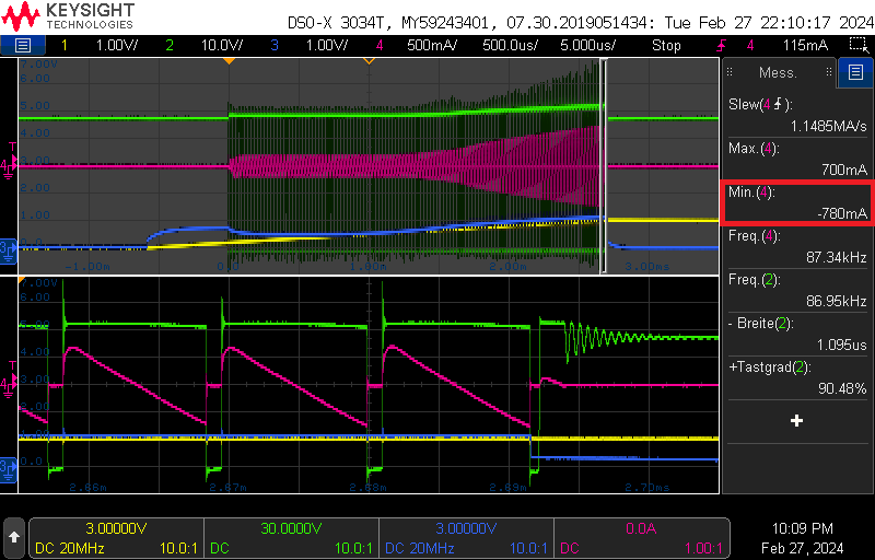
Figure: failed startup
(1: SS, 2: SW, 3: COMP, 4: current through active clamp capacitor on SNBR)
Details of our design:
5V output voltage
6W output power
Startup through PSE (47V)
3:1 Transformer with Lp 30µH (primary leakage 0,9µH)
300kHz switching frequency
Discontinuous Current Mode
4,7µF SNBR capacitor
220nF SS capacitor
Regards
Philipp