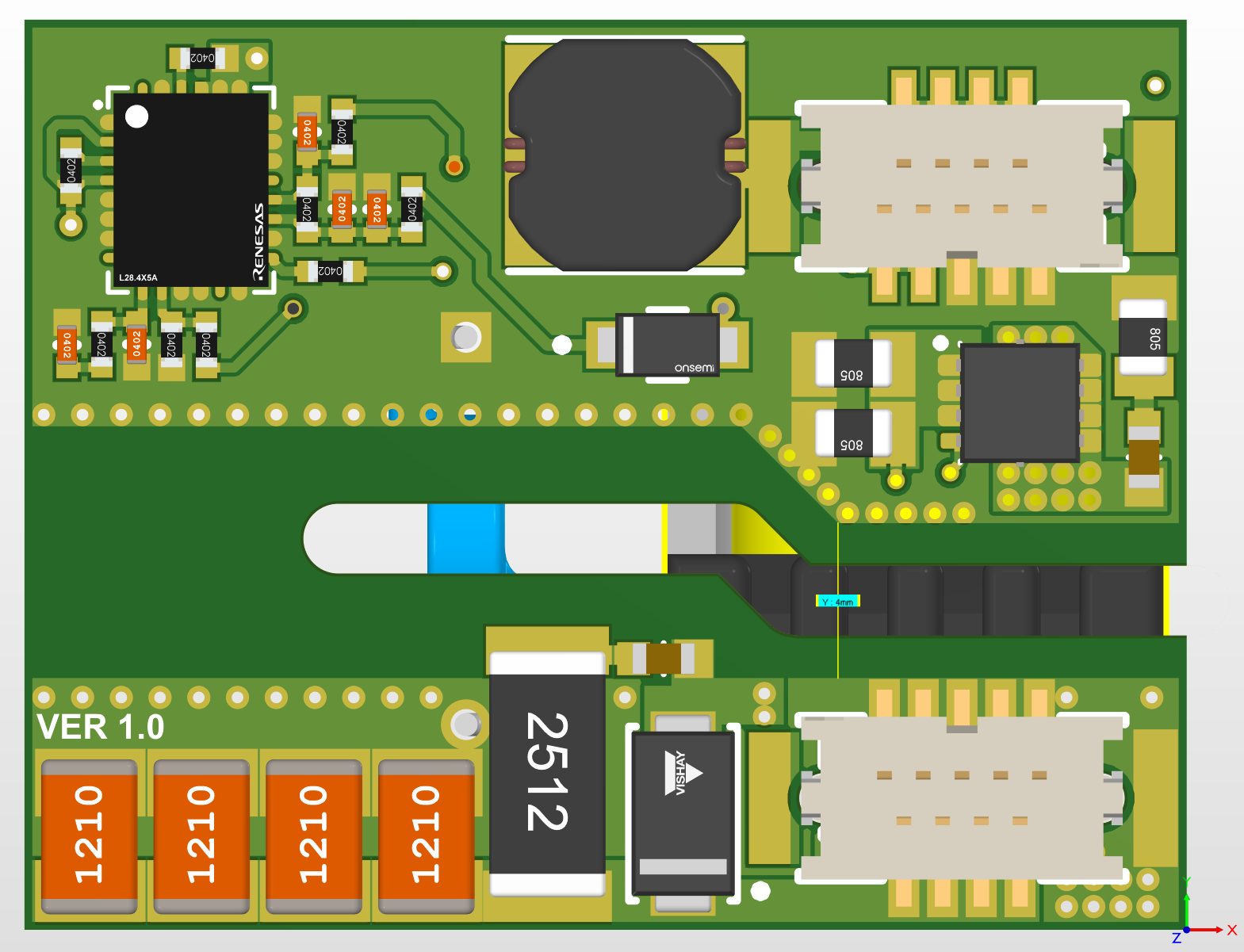
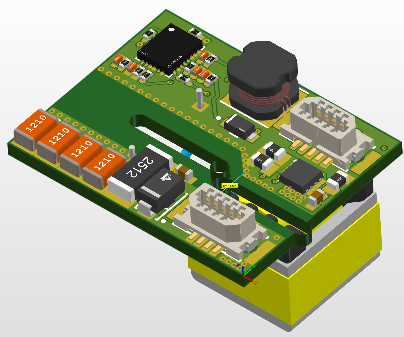
Hello,
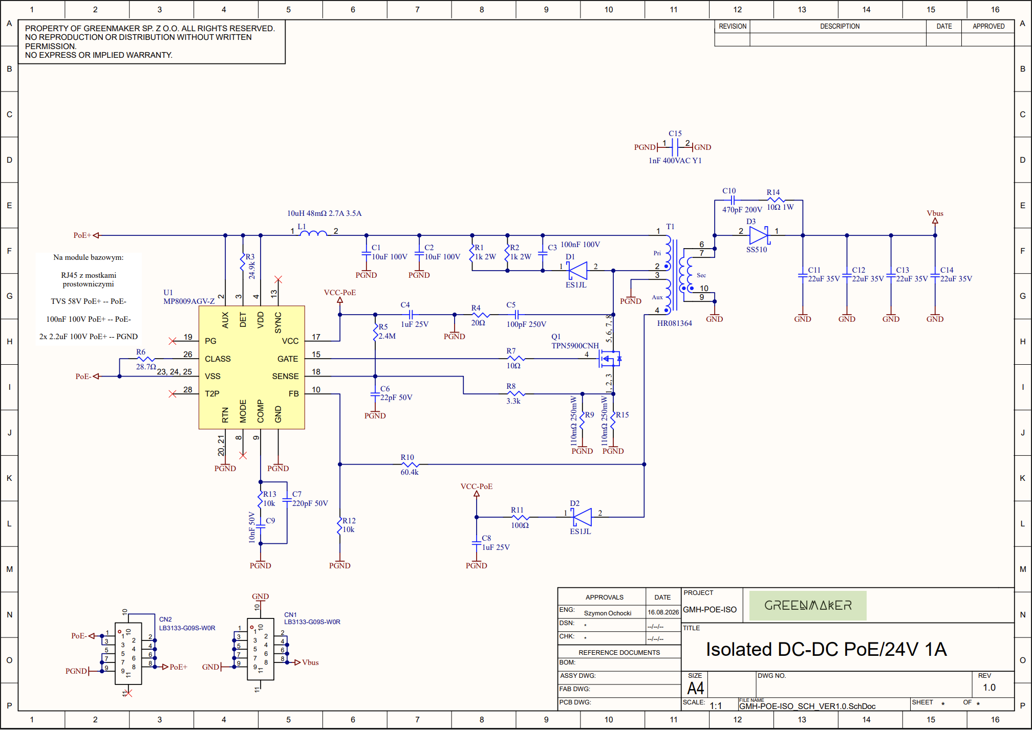
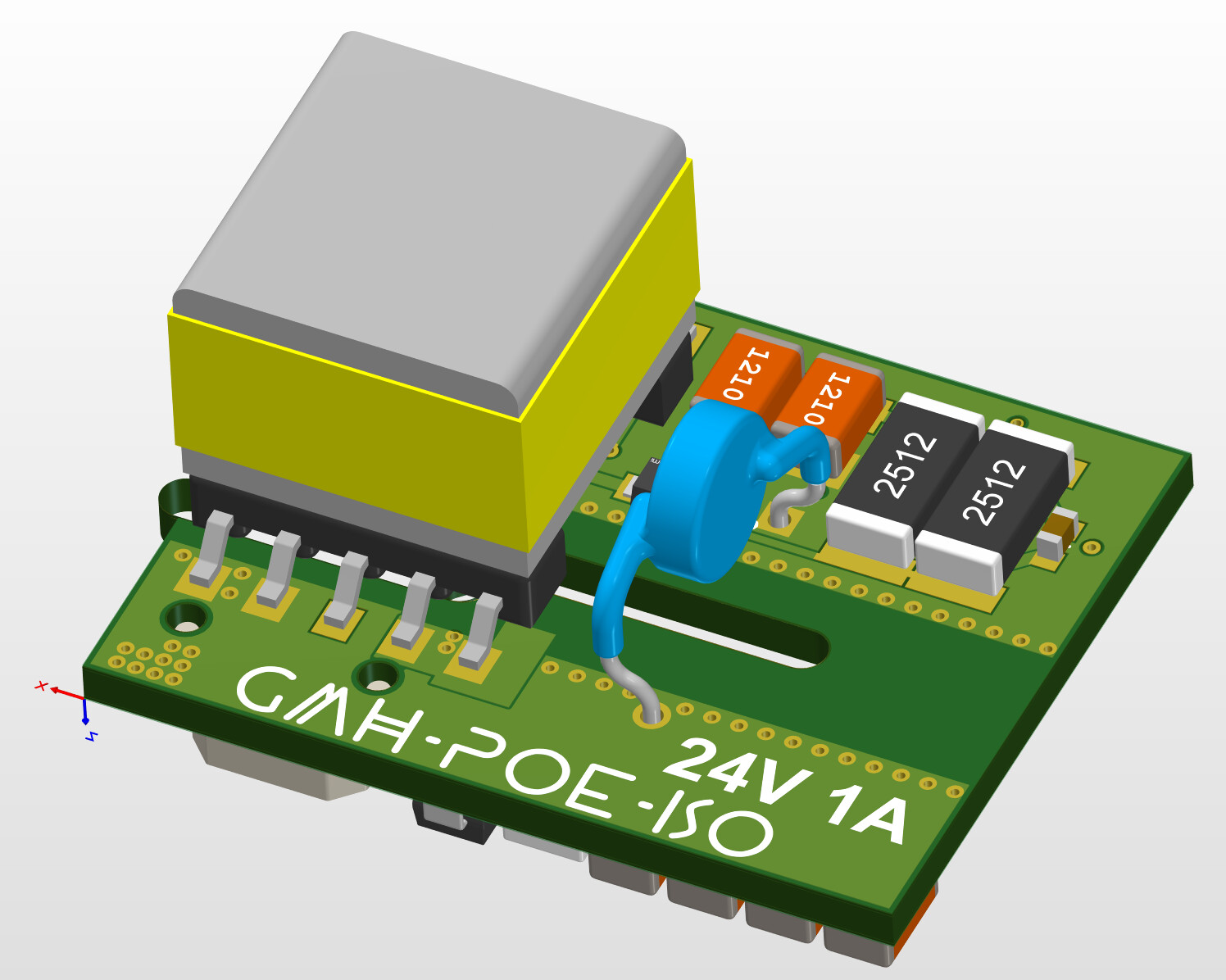
I am designing a PoE power module for my controller. The target output is 24 V / 1 A.
I am using:
-
MP8009AGV-Z
-
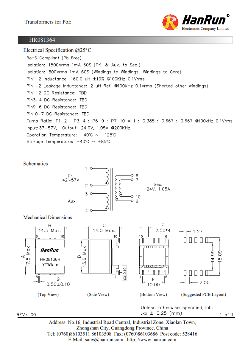
transformer HR081364
-
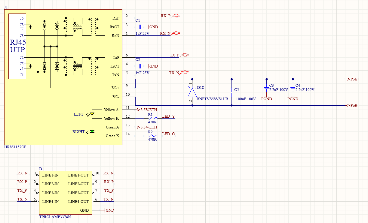
RJ45 jack with integrated rectifier bridges HR851157CE
I would appreciate help reviewing the schematic and my calculations.
From my calculations, the MOSFET drain voltage should be around 120 V (the MOSFET VDS is 150 V).
The regulated output (before the diode drop) is about 24.4 V, which after subtracting the forward drop of D3 should give ~24 V at the output.
I am not adding a dummy/minimum load on the board, because this rail will supply downstream circuitry. For bench testing I will add a load manually.
In its current form, is there a realistic chance of passing EMI tests?
Thank you in advance.