Good day,
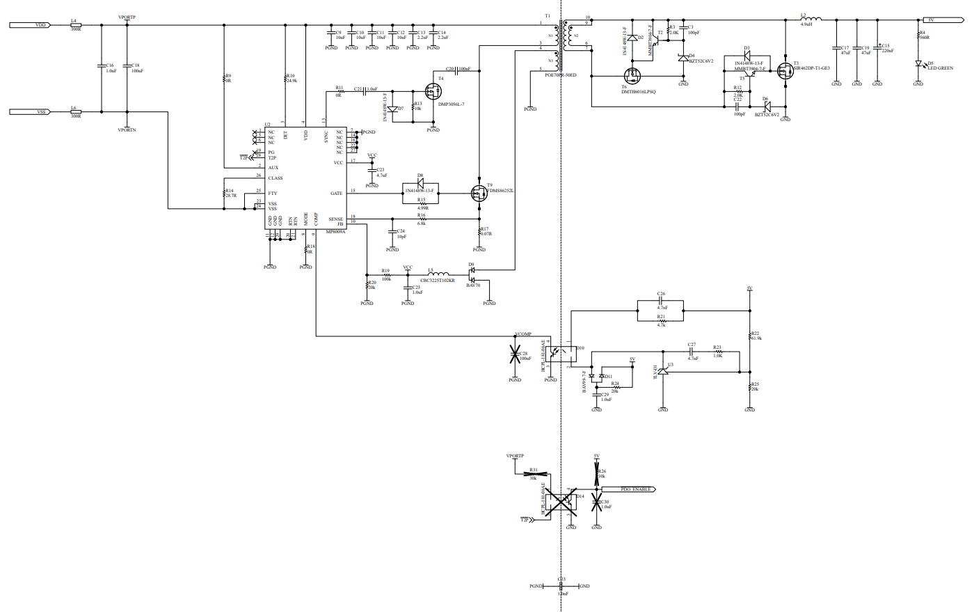
I have integrated the MP8009a in an SSR forward topology. The circuit was based entirely on the example typical application from the datasheet. However, I am not able to obtain the 5V output on secondary side.
The circuit I have now, uses about 6mA on a 50V input. Every 320ms, the gate is driven by a 10Vpp pulse train for about 10ms. The resulting output is a rise in voltage to 2.2V which then quickly slopes down to 0 in the same 320ms timeframe.
Any help/advice would be greatly appreciated.