Hello,
I’m trying to adjust the EV8008’s reference circuit so that the output is 5V.
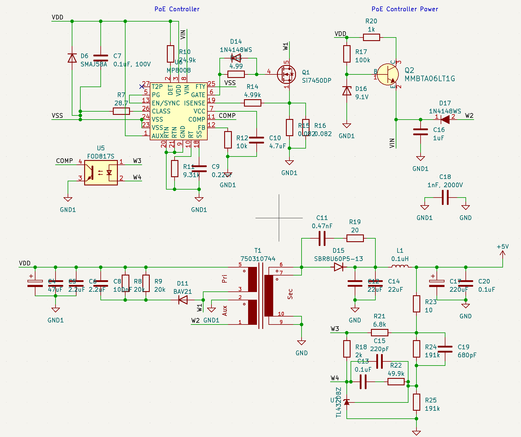
I am using the Wurth 750310744 transformer, and I adjusted the voltage divider resistor in the feedback circuit, however I am not getting the right voltage out.
The two resistors (R24 & R25 in my schematic) are now both 191k, however the output voltage I’m reading is 8.4V instead of 5V.
I measured the reference voltage output by the TL431 and it’s correct (2.5V).
Is there anything I need to change in the circuit?
Any help would be greatly appreciated.
Thanks
schematic says TL432 which has a different pinout. If Vout is too high the the output of the 432 should be lower than 2.5V . The only part of teh 432 that should always be 2.5V is the ref pin.
I’m using TL432LI because TL431’s pinout doesn’t match the PCB layout of EV8008. TL432LI is more appropriate, see MP8008 PoE Feedback Circuit reference voltage .
In any case, yes, the ref pin measures 2.5V, and the output (cathode) is approx 1.1V.
Any help would be appreciated, thanks.
So that sounds like a happy 432, I would double check/replace your output voltage divider, I would wonder if maybe a C19 or C15 was leaky.
Thanks for this. I doubt it’s a faulty component issue since I have two identical boards and both are behaving exactly the same way, hence why I am leaning more towards a design issue than a hardware one.
Let’s see if one of the MPS engineers can give us their 2 cents on it, and I’ll then see what the best options are.
Thanks!
What do I need to do to get an MPS engineer to respond here? @vinh.tran ?
Hello nzapponi,
I apologize for the late reply. Could I also get your Vin, load current values and what the octocoupler value is?
Thank you,
Vinh Tran
Hi @vinh.tran, thanks for the reply!
- VDD is 47.6 V
- Vin is 8.57 V
- Load current should be ~ 3A but I’ve been testing without a load as the current voltage would break anything I’d connect.
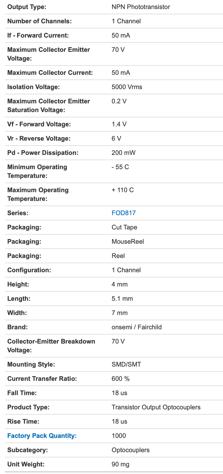
The optocoupler is a FOD817SD, with the following characteristics:
Datasheet is here: https://www.mouser.co.uk/datasheet/2/308/1/FOD814_D-2313902.pdf
Thanks!
Hi @vinh.tran, do you have any updates about this?
I need to resolve the issue urgently and I’m not sure where else to ask.
Thanks.
Hi nzapponi,
What are the voltage values on your input and output for the octocoupler?
Thanks,
Vinh Tran
Hi @vinh.tran,
Thanks for the reply!
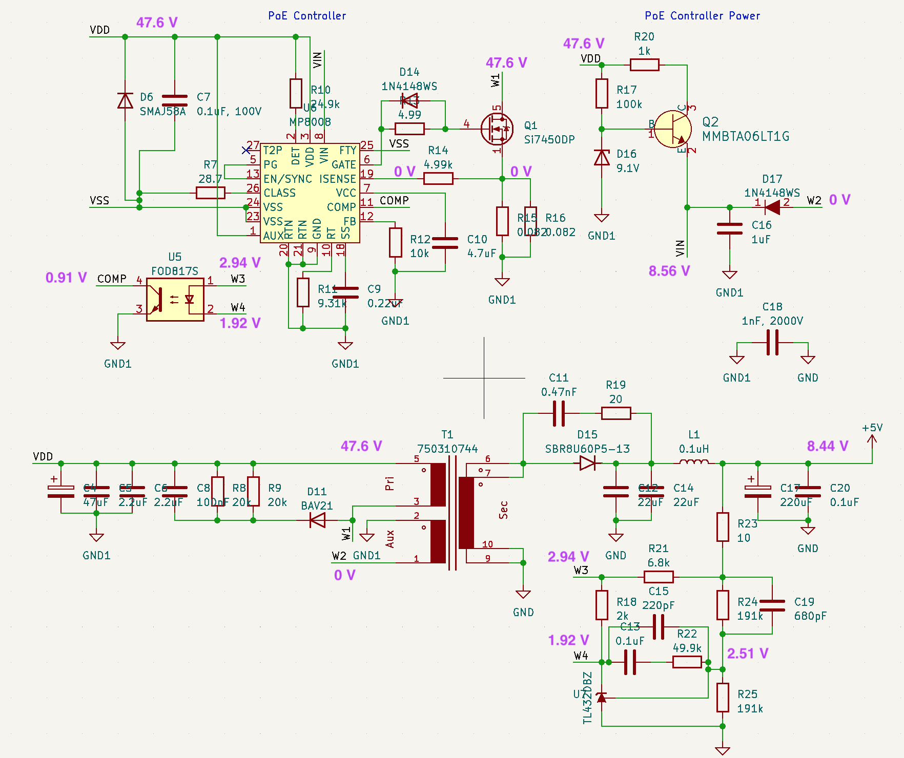
Here are the voltage measurements across the entire circuit, including on the input and output of the optocoupler.
Let me know your thoughts, thanks!
Nick
Hello nzapponi,
I reached out to someone who said there might be something wrong with your octocoupler/reference circuit. They said the 5V output and 2.5V reference leave little headroom for biasing the opto diode and TL432. The TL432 needs 1.0mA minimum and the opto-diode will need over 1.0mA. To fix this, they suggested lowering R21 to be much lower than 2.5k, around 1.2k.
Or the better solution would to be replace the TL432 with a TL431 or ZL431 with a 1.24 reference. Compensation will need to be adjusted also.
Thank you,
Vinh Tran
1 Like
Thank you for the suggestion @vinh.tran!
I’ll try lowering R21 to 1.2k and see if it solves the issue.
Otherwise, regarding option 2, in terms of adjusting compensation, you mean only adjusting R23 and R24 to the correct ratio for the 1.24V voltage reference, is that right?
Thanks again
@vinh.tran thank you so much for your help, lowering R21 has fixed the issue!!
Best
Nick