I designed a circuit for PoE with MP8007GV-P. I followed the reference guide as possible.
Here are the values:
inductor: 500uH
output voltage 9V.
current limit & resistor: 0.35A with 300K
Power at minimum frequency (10kHz): 300mW
Output caps: 100uF & 22uF.
The issue is:
- Have produced 24 boards.
- 20 works perfectly!
- 4 wasn’t working due to MP8007 turn off due to vout overshoot to 11.6V.
- 2/4 decide to work by their own!
- I add 200 ohm dummy to one and work
- I added 100 ohm dummy load for last one, worked for a bit, but didn’t work again!
The load is connected to buck converter to step it down to 5V and it derive a Raspberry pi. There are some load if the voltage was stable for few seconds.
My question is why the behavior is not consistent?
Do I need a 300mW dummy load for all boards?
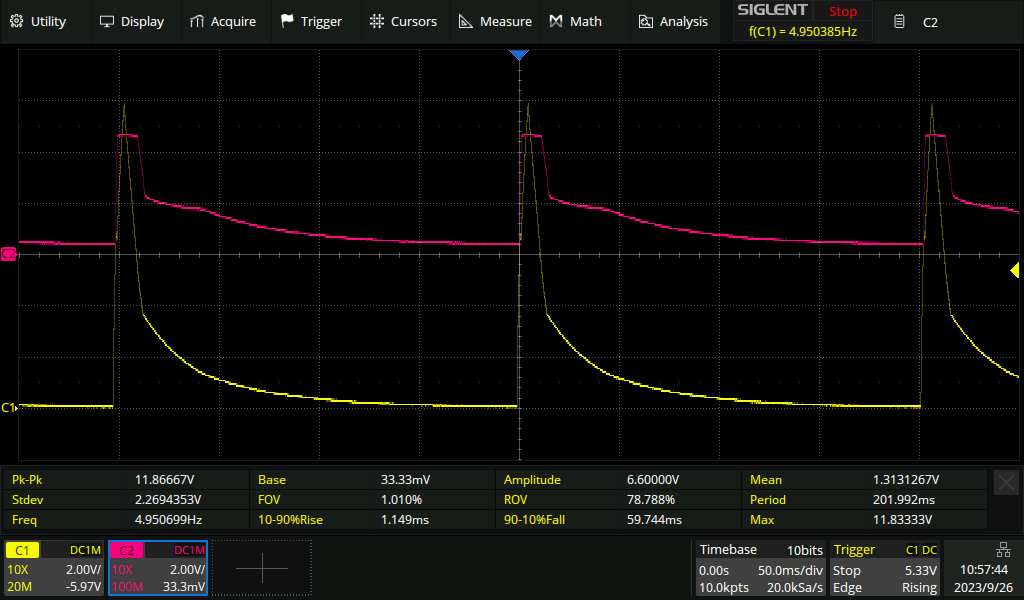
I attached the vout of the PoE flyback & the buck regulator.
Internet weirdo here, I think there is a minimum load requirement of 10mA in order that the PD still knows there is a proper PoE device on the other end. You wouldn’t want to put 48V on the wires to a normal ethernet device. That would blow up the Bob Smith resistor. I would try adding 250mW of load to the failing units and see if now they pass.
Hi @jshannon ,
I already have a load of more than 10mA on the PoE output.
BTW, I tested with both standard and non-standard PoE injectors.
The non-standard PoE injectors will have the 48V all of the time at the ethernet lines! No negotiation between the PSE & PD in this type of injector.
But it looks that needs more load. But this is not efficient at all to have a 250mW dummy load!
My circuit normal operating will consume 1W. is is 25% of it.
Load has to be over 10mA on the input side. Can you have a dummy load that is turned off by the operation of your circuit? What is the requriement for efficiency at these low power levels? Other than a generic is ought to be better feeling?
Thanks @jshannon .
When I tested it, I used both non-standard & standard PoE injectors.
The non-standard one, doesn’t have any negotiation, the 48V will be on all the time on the pins.
So it is only the MP8007 was turning ON & OFF.
So this is really just about the flyback part. What is the peak current the buck can draw? Does it have an pin that you could use as an undervoltage lockout or EN to prevent it turning on before the flyback has established nearly final voltage.
Yeah, it is only on the flyback.
The buck regulator can draw up to 1A. It has under voltage protection, it will not turn on till the input voltage is greater than ~4.3V.
In the screen shot I uploaded above, you can see when the buck converter is turned ON & OFF when the Flyback output voltage exceeds the limits.
I noticed that I did something wrong in the schematics & PCB, but it is not related to this issue.
I connected both the VSS & PGND together next to RTN.
But I remove this connection. still has the same issue.
Can you remove the downstream buck converter and just see if the flyback can work by itself. In other words is it the flyback, or an interaction between the flyback and the buck
Hi @jshannon .
Even if I added more load before the buck?
should it make a difference?
Cause I already did that; adding more load before the buck with buck exists. And this didn’t work as well.