Thanks for your question.
Please provide a diagram of how you are connecting the part and the voltage on each input (VCC, FG/RD, PWM), as well as everything you are measuring on the outputs.
Are you measuring 3.8V without even applying VCC?
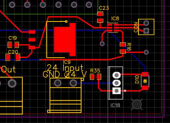
the input is 24 volt and then it is regulated to 5 volt with TI LDO. I measured it and I am getting exactly 5 volt.
C23 is the capacitor of the voltage in pin. I put 10 uF. also I checked 2.2 uF too.
R16 is the pwm resistor. I put 50 ohm first. (from your datasheet) But the ldo got very hot. Then I tried 45-50 kohm. nothing changed. Also I tried without resistor.
without making any connection to pwm line. I gave power. the fan started to spin a couple turns and stopped. waiting a while and the fan started spinning a couple of turns and stopped.
after this attempt, I make connection of pwm line. nothing changed.
Apologies for the delayed response.
Do you have a more clear schematic? It’s difficult to decipher how you are connecting the part from the board layout. Could you also provide scope captures of VCC, PWM, OUT1 and OUT2?
Hello Cindy.
I bought MPS6650 from Digikey for development of fan circuit. I am using simple application circuit is as described in datasheet. No PWN given to the circuir for trial.
Motor stops running after 1-2 second run. Please advise what correction to be done. so that my motor can run freely for trial.