Hi Team,
We are using the MP6619 ic to drive 2 solenoid relays, Unfortuanly this is not working as expected.
So we would like clarify few points before proceeding further.
- Whether MP6619 is recommended for solenoid driver ? as per datashet this part number is suitable for solenoid driver.
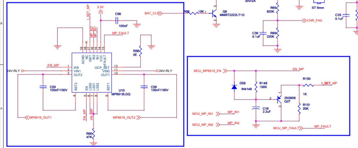
- If yes. Could you please review the below schematic and share your feedback.
- if our selection was wrong, Kindly suggest the solenoid driver with 2 channel.
Well two things spring out. VCC is a 5V output from an internal LDO so it looks like it is powering a 3.3V rail. That might cause a problem. The second thing is the OCP is set with a weird value, I would suggest removing it for now.
Hi Team,
Thanks for the timely support.
- The incorrect connection of VCC to the external 3.3V rail has been rectified. After correction, VCC is now showing the expected 4.9V.
- The OCP 0E ohm value has been removed as suggested, but regrettably, the 24V output is still not appearing at the output pin.
- Upon enabling the EN and IN1 pins, the BST1 pin registers 4.2V, but unfortunately, there is no voltage detected at the OUT1 pin.
- It appears that the IFB and LSS pins were connected to ground using a 47K value resistor. However, based on the datasheet specifications indicating a requirement of 40 meg for a 200mV trip voltage, this resistance value might be incorrect.
- In addition to above points, Fault pin always in pull down state, I suspect that there is a OCP, OVP issues due to invalid resistor setting.
- Given the urgency due to the customer delivery issue, we kindly request your support in resolving the circuit problem. Any guidance or assistance you can provide in getting the circuit operational would be immensely helpful in unblocking the delivery.
We appreciate your timely assistance in rectifying these issues
Just an internet weirdo with time on my hands, not on a team. The resistor on LSS is way way too high
The trip threshold is 200mV and the sense value is 47k so that means that OCP trips sat 4uA give or take
I suggest you figure out what the solenoid current will be by dividing the coil resistance into 24V.
Then select R60 so that that coil current working against R60 is less than 200 mV
If for example the solenoid resistance was 24 ohms, then the current would be 1A. 1A through R60 and less than 200mV . Lets use 100mohm to put the protection level at 2A.
1 Like
Hi Jshannon,
We have measured the resistance of the solenoid coil, which reads 70 ohms and Operation voltage is 24V. Could you please provide the formula used to calculate the RSEN (sense resistor) value?
I’m Quite confused to apply formula for below explanation,
f for example the solenoid resistance was 24 ohms, then the current would be 1A. 1A through R60 and less than 200mV . Lets use 100mohm to put the protection level at 2A.
Could you please support me the RSEN value considering the 70 ohm of solenoid resistance and 24V of operation voltage?
24 volts and 70 ohms The solenoie current will be 350mA
I=V/R
That current flows out the LSS pin through the sense resistor. If the voltage is over 200mV the OCP trips.
So again V=IR if we want 100mv under normal conditions R=V/I = 0.1/0.35 0.28 ohms.
And the dissipation in the resistor is I^2R or 0.35^2 * 0.28 34 mW so an 0805 surface mount would be plenty for that function.
In the short term I bet you can just short it. To see if you can drive the solenoid
Hi Jshannon,
We made modifications by grounding the RSEN pin and setting the EN and INV1 pins to high using the MCU. Despite keeping INV1 high, the output exhibits a pulsating signal instead of a stable one.
Additionally, when the BST1 capacitor is connected in series with a 10K resistor, it reports approximately a 6-volt pulse. However, upon removing the 10K resistor and connecting only the capacitor, it registers a pulse voltage ranging between 20 to 30 volts.
Could you kindly provide guidance on why the output is pulsating despite the steady INV1 status? Also, any insights into the voltage discrepancy observed when connecting the capacitor differently would be greatly appreciated
Also, the fault PIN status remains 0 despite being pulled up. Any insights on why the output behaves this way and the fault PIN status issue?
Thanks for your support in advance.
What is all the junk in the lower right hand box? Looks like you are trying to perhaps implement a hit and hold circuit? For now I would consider removing it, simpler is better to start. If the fault pin is low the IC is unhappy for some reason OCP or OVP
Hi Jshannon,
Yes, I previously added a lower right-hand box for hit and hold purposes, but it has been removed since.
There are three reasons why the fault pin remains LOW, indicating the IC’s dissatisfaction:
- OVP - We’ve grounded components such as IFB, LSSO, LSS1, LSS2, allowing for 0.4 A, as discussed earlier.
- OCP - The OCP_SET remains open, resulting in a trip voltage of 200mV.
- OTP - The IC’s temperature remains within the acceptable range and there is no IC shutdown noticed.
Reasons 2 and 3 have been eliminated from consideration. We suspect that a short to Ground in the RSEN value, rather than the intended 0.28 Ohm series connection, might be causing the pulsed output signal and forcing the fault pin to remain LOW.
What happens if you disconnect the solenoid? You should get a pulse then. Maybe substitute resistors of ever decreasing value after that.
When the solenoid is disconnected, no output pulse is observed in the OUT1 pin. Should we proceed with connecting the resistor to the RSEN pin as per the calculated value
I got no idea, maybe you killed the chip? But yes I would rebuild with the calculated values. Do you know the solenoid is good?
Yes, the solenoid is confirmed to be functional. We conducted a separate test using 24 volts, and it operated without any issues. Nonetheless, I’ve proceeded to order an evaluation board for additional testing purposes.
I’ve made another observation: in the current circuit, the ground is common across all sections, whereas in the sample circuit, the ground is separated.
I’m planning to modify the circuit, as like evaluation board circuit. Do you have any suggestions or recommendations that I should consider before redesigning the PCB?