Hello, I just received the EVQ6615-QK-00A evaluation board. I am new to MPS products and would like to clarify some things about it’s operation before hooking things up. The application is a 12VDC motor driving an acme screw similar to a seat adjustment.
I am looking for the simplest way to evaluate this board before putting a lot of time into developing firmware for a microcontroller. According to the Quick Start Guide, I would put +12V between Vin+ and Vin-, connect a 5V source between terminal 3P3 and 3P3_GND pins, and enable the chip with SW1.
The way the input modes, etc are described in the data sheet is a little confusing to me. At this stage, I am not interested in looking SOA & SOB current outputs or doing any PWM. I simply want to make the motor spin one way and then the other. I also want to test the overcurrent protection which I can set with SW2 to latch off or retry mode. Can you give me some direction to get started? Thank you.
After studying the datasheet a little more I would like to make my question more specific. If I choose input mode “00” via SW3 & SW4, does the “ENx” and “PWMx” in Table 2 mean that ENA&ENB be tied together and PWMA&PWMB be tied together?
Thanks for adding more specific details to your question here. I will look into this and get back to you on this thread.
Best,
Krishan
Hello again,
Figured I would give you a quick update on some minimal setup instructions since you just want directional control without PWM and current sensing:
- Apply 12V between Vin and GND.
- Apply 5V to the logic supply
- Enable the IC by pulling SW1 high, perhaps to the same 5V as the logic power supply.
For your more specific question on the following:
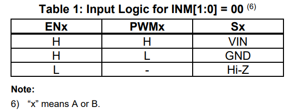
You don’t need to tie these signals together manually. Instead, you drive IN1 - IN4 with the following logic where your motor is connected between SA and SB:
- Forward: IN1 = High, IN2 = Low
- Reverse: IN1 = Low, IN2 = High
- Brake: IN1 = IN2
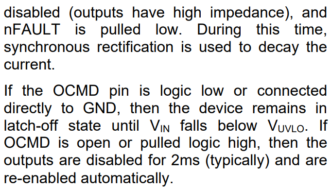
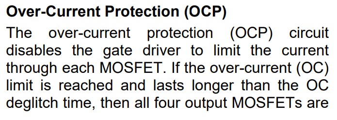
For testing overcurrent protection and setting retry/latch behavior, OCMD is the pin that sets the fault response mode where:
- OCMD (Open) = Retry Mode
- OCMD (Pulled to GND) = Latch-off Mode
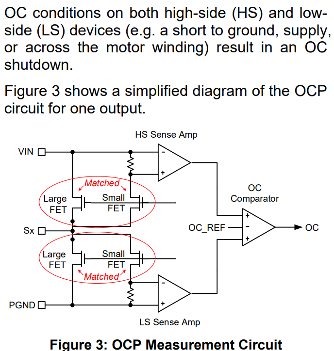
You can trigger a fault by shorting the output briefly and observe the behavior.
Here is some more info on this from the daatsheet: