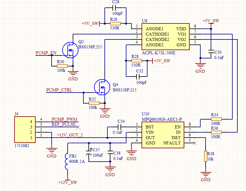
I am designing a driver for a 12V pump. However is the pump is not connected MP6610 output is measure with multimeter is 12V. The output voltage will drop to about 4V when the pump is connected. The pump is working fine if it is connected directly to a 12V power supply. Any advise on how to resolve this issue ?. Thank you.
Currently looking into this issue. I will respond once on this thread once I come up with a solution.
Best,
Krishan
Sorry for stepping in like this, but wondering a little bit - how much current does the pump draw? Because i see you have 10k resistor on ISET pin
No worries @dexaselectronics, this is a community forum after all. But I do think you are onto something here.
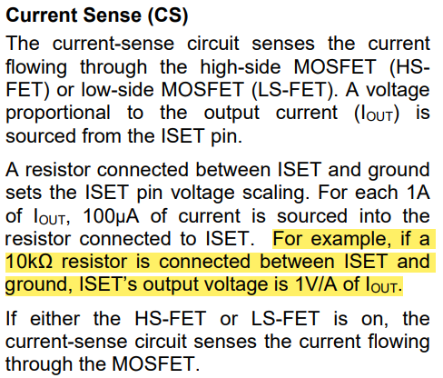
There doesn’t seem to be anything else that is suspicious regarding the schematic for the MP6610 here. The datasheet has this to say about ISET and the resistor having been set to 10k:
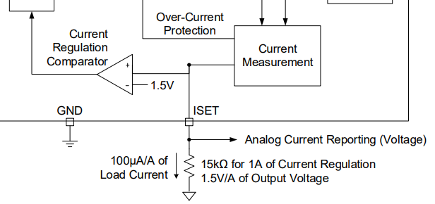
This is also detailed in the functional block diagram:
Is this enough for the MCU to properly operate here? This would be worth it to check the MCU datasheet if this is not enough.
Hi … the mcu is only used to generate the PUMP_EN, PUMP_CTRL, and PWM signal (3.3V logic level). The voltage across the ISET resistor is not monitored by the mcu.
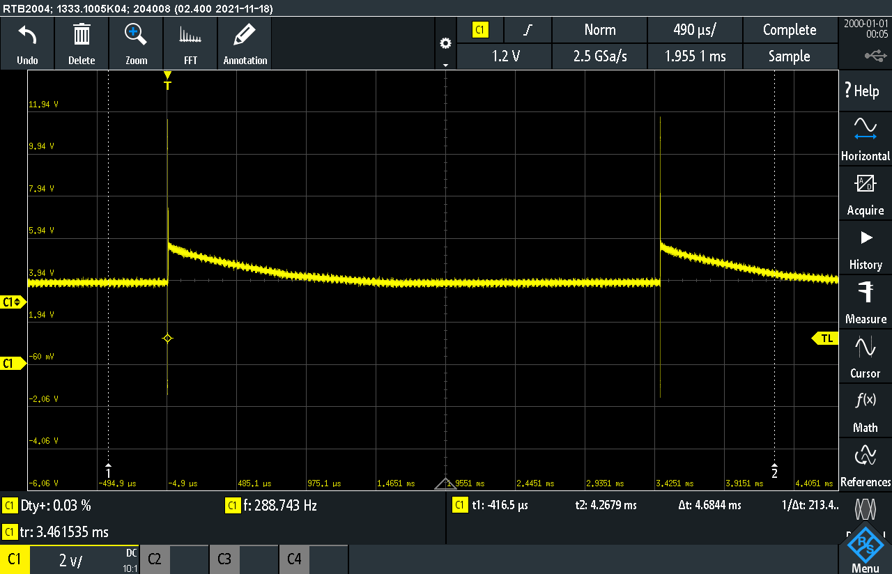
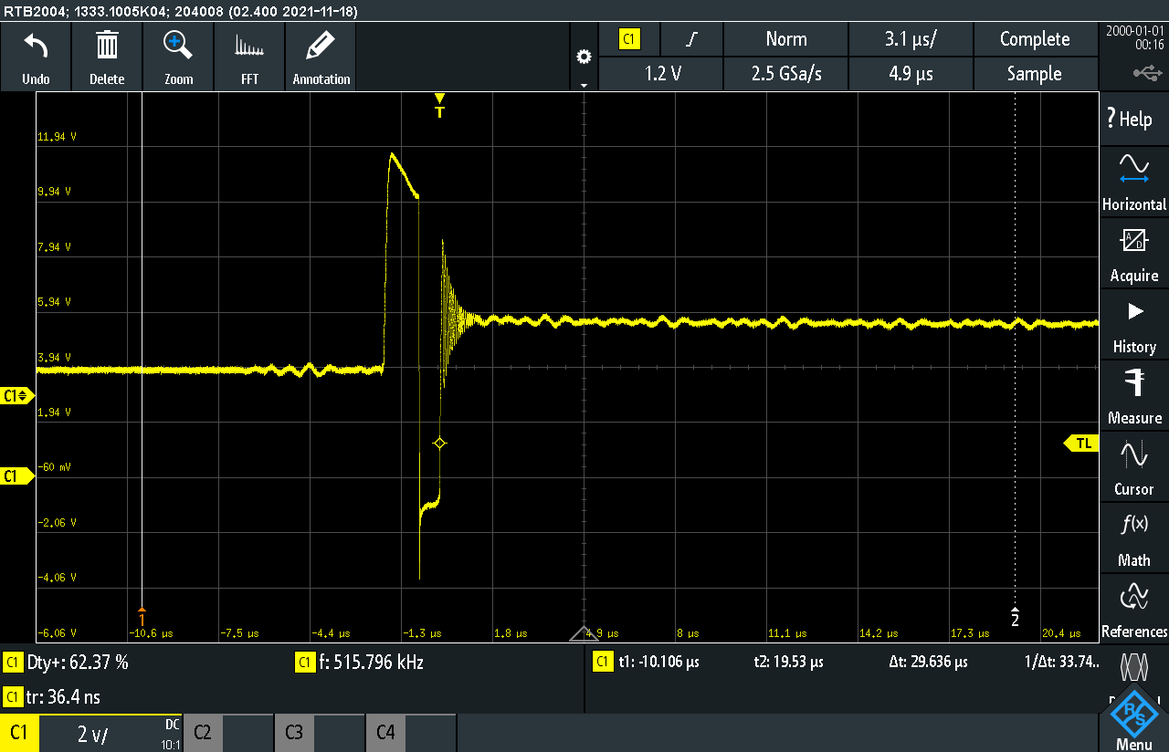
Do you have waveforms to show for this issue?
motor wiring:
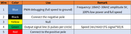
for additional information the motor used is brushless dc motor 12VDC 3W with PWM speed control.
Thanks for sharing these waveforms and apologies for the delayed response on this issue. I see the initial 12V level followed by the fast sag to 4V. This decay seems to suggest power loss or clamping. It is likely that the FETs aren’t fully staying on.
Here are some possible reasons as to why this could be happening based on what is shown:
-
The MP6610S current limit or Under Voltage Lockout may be triggered. This could be due to the selection of your external FETs, where the startup current may not be able to handle motor startup current. The BSS138P FETs are small signal FETs (less than 1A). Try a FET with a continuous rating of above 3A.
-
The Rds On of the FETs may be too high, where a 100k gate resistor is far too large as suggested by the waveforms. This slows down switching, increasing power loss, yielding a FET that may not turn all the way on. With whatever FETs are chosen, find something with a lower Rds On, perhaps less than 50mOhms.
Upon switching out to more appropriate external FETs, I have two other suggestions if this doesn’t completely solve the issue:
-
The Optocoupler Drive may also be insufficient. While the ACPL-K73L is good for signal isolation, it would be good to check if enough current is being sourced to properly drive enough gate capacitance.
-
The datasheet recommends at least 100uF of bulk capacitance near the motor or the FETs (which is satisfied by C37 already). If all else fails, try increasing the value of C38 as this may help to further maintain stability at the input.
Hope these debugging steps prove helpful. In conclusion, it would be most important to start with replacing the FETs and then focus on debug steps 3 and 4. Let me know how things go.
Best,
Krishan