Hello everyone!
I am struggling with valid communication via SPI to MP6606.
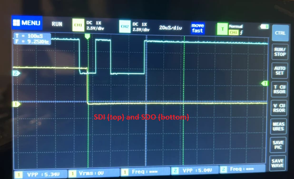
From HW part all voltage levels looks good, but sending in the loop 8-Bit transaction doesn’t return any SDO signal.
SPI settings:
- frequency: ~125kHz
- CPOL = 0 / CPHA = 0
- nSCS is non-Automatic (manual selection)
- Data to send in SPI: 0x30
Voltages:
- VIN = ~12.3V
- VCLAMP = 11.99V
- RESET, ENBL = 5.0V
- OUT1-OUT8 = 12.31V
Please, review my inputs and recommend what could be a problem.
Thank you in advance!
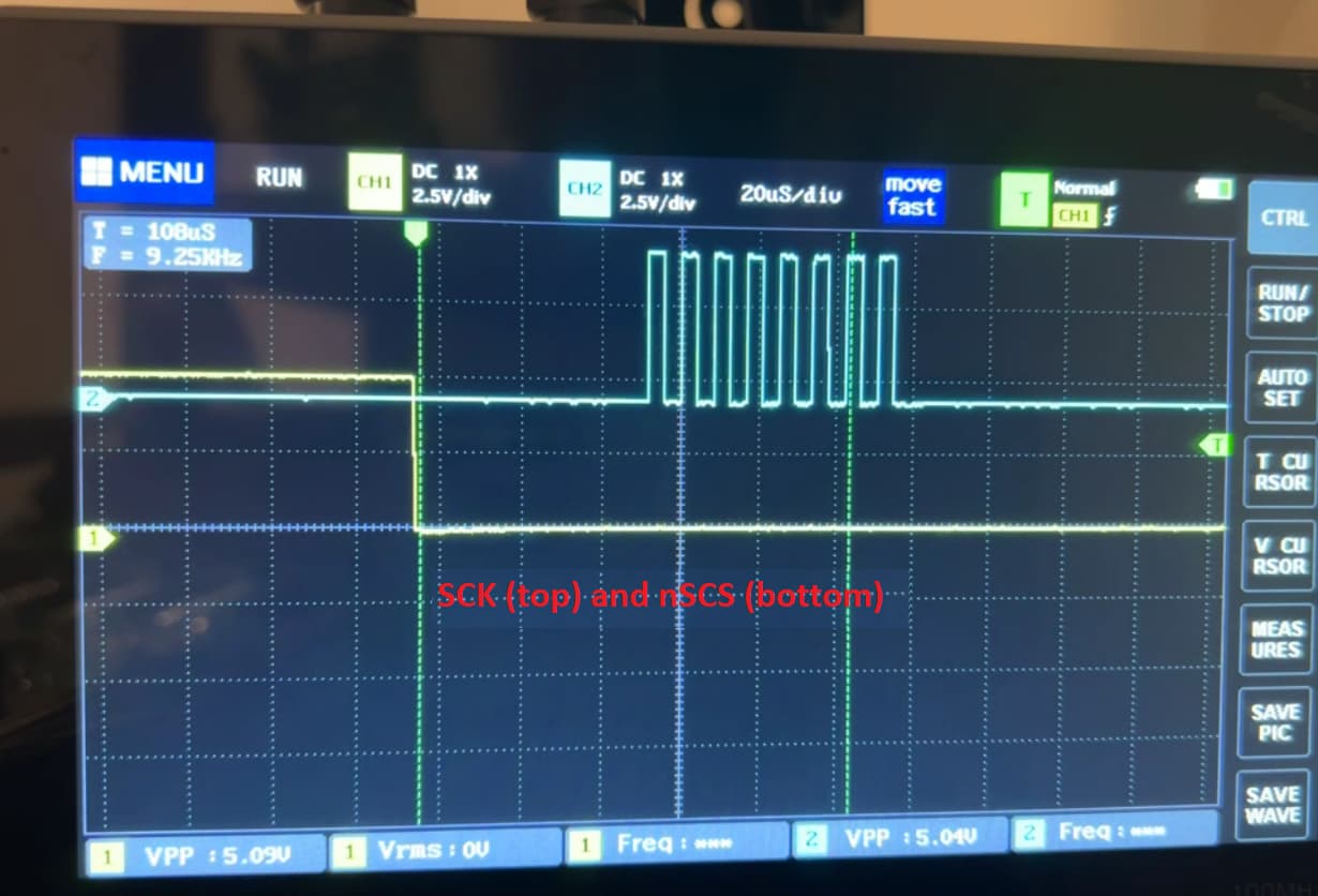
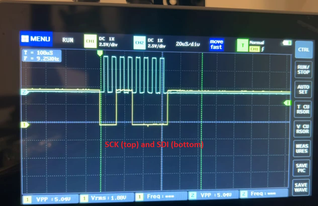
Diagrams of signals:
Please, be aware that RISING edge of nSCS is set after 1ms (manual chip select), but not shown on the diagram.
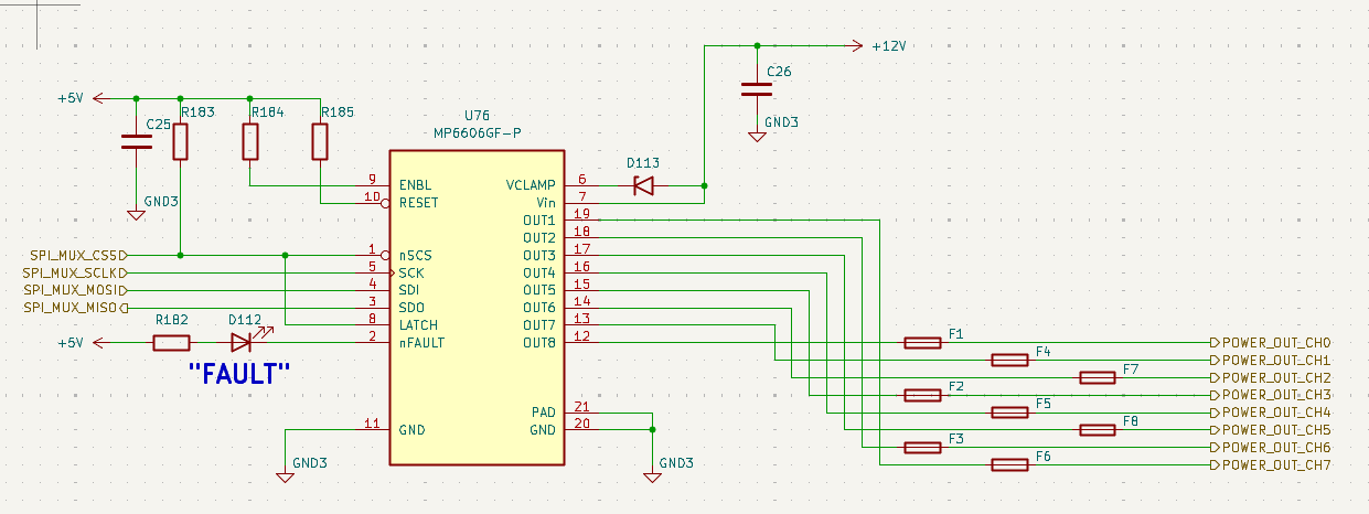
I also attached schematic here for your reference.
Kind regards, Yurii
Hello, community!
I’ve found the root-cause of problem. It was misguidance in the datasheet info.
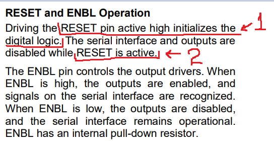
Please, look at this fragment:
Statement 1: says if RESET pin is high → I expect the SPI availability because digital logic is initialized
Statement 2: says OUTputs disabled when RESET pin is active (what is Active?) → I expect when RESET pin is high, then digital part and OUTputs are enabled.
Please, be aware, in the microcontroller world, RESET pin in LOW leads to reset device condition, but this chip works differently: RESET pin in HIGH leads to reset condition.
Solution:
- leave RESET pin in LOW to enable the outputs and to be able to communicate via SPI
@Rubas.FAE or your colleagues, please improve the datasheet explanation to avoid misunderstanding in the future. Thank you in advance!