Hi, I am developing a PCB to run a BLDC motor using the MP6540HA driver.
I have realized that the current sensing signals SOA, SOB and SOC have a current spike on a rising edge of the PWM signal.
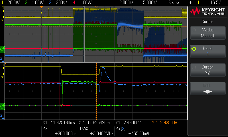
As I assumed that the cause was an internal crosstalk in the chip, I increased the dead time considerably (from 260 ns to 2 us see picture below), but the current spikes are still there.
The oscilloscope picture was taken of it during motor startup.
Probe 1 (yellow): Voltage Phase A
Probe 2 (green): LSA (low-side MOSFET)
Probe 3 (blue): SOB (current sensing signal)
Probe 4 (red): HSA (high-side MOSFET)
260 ns dead time:
Do you have the same experience and do you have a solution?
Marco B.
Hi Marco,
Are you seeing this spike for SOA?
Best Regards,
Yu
Hi Yu,
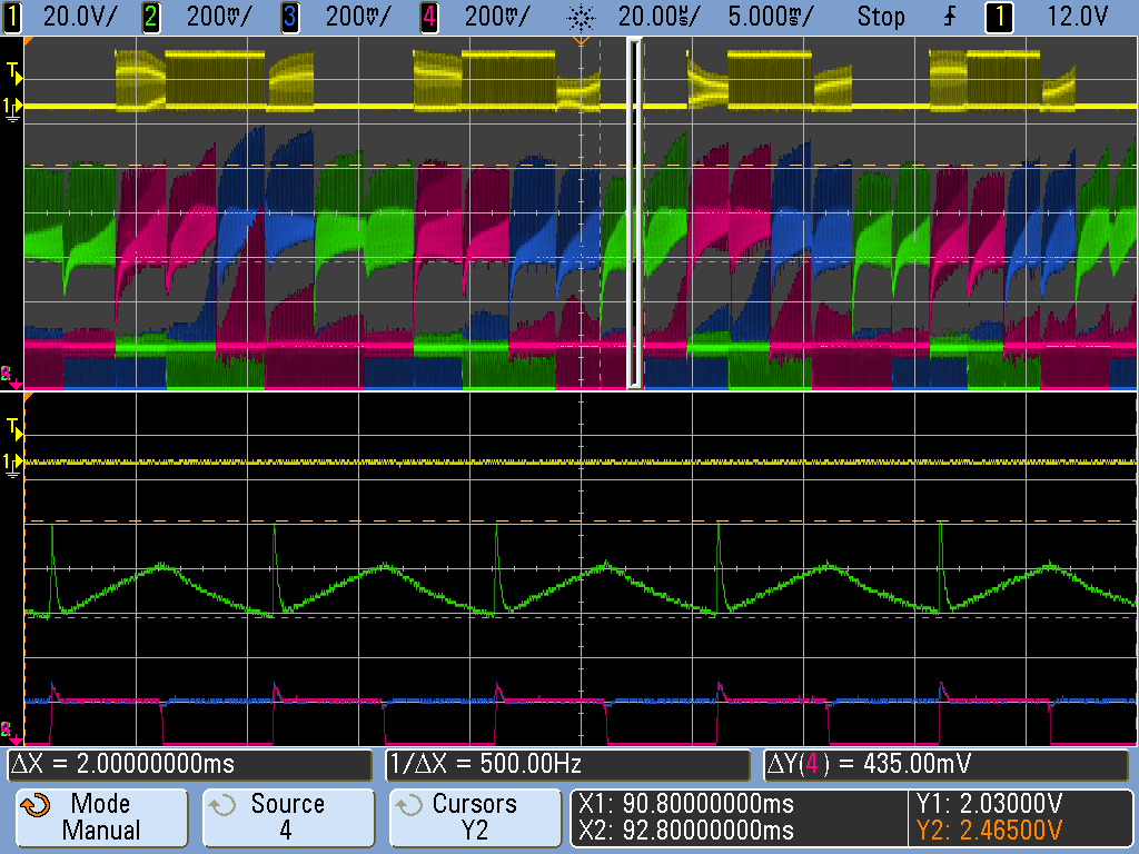
The current spikes occur on all three current sensing signals (SOA, SOB and SOC). This oscilloscope picture shows the current sensing signal SOA just with 2 us dead time.
Best Regards
Marco
Hi Yu,
Yes, I’m seeing the spikes for all three signals (SOA, SOB and SOC).
Probe 1 (yellow): Voltage Phase A
Probe 2 (green): SOA (current sensing signal)
Probe 3 (blue): SOB (current sensing signal)
Probe 4 (red): SOC (current sensing signal)
Zoom SOA during Startup:
Best Regards,
Marco
Hi Marco, it’s likely this is a known limitation of the part. The internal amplifiers will not have perfect common mode rejection ratio, and you’re seeing this leak through to the current sense outputs. This ripple is visible on the first plot on page nine of the datasheet (steady state (duty cycle = 10%).
Because of the ripple also from the motor inductance, it’s common to use edge triggered ADC capture in motor drive applications like this.
It’s tempting but perhaps unwise to try to filter out this ripple entirely with an RC filter below the cut off frequency of the PWM. Because the ripple only happens in one direction, this would add a DC offset to your measurement. Depending on your application, this may be unacceptable.
Pay special attention to anything you’ve added to the output phases that might change the phase voltage edge rate - this might impact the intended edge and cause more common mode noise to get through the amplifier. In particular, external ESD diodes with high parasitic capacitance might be to blame here, or high capacitive coupling to the ground plane of your PCBA. Good luck.
1 Like