I’m really struggling with the bring up of a new PCB incorporating the MP6540H. I would very much like to get the MP device working (so I don’t have to go back to the ancient-but-works DRV8313).
I’m trying to drive a 3 phase BLDC motor using PWM. I’ve incorporated the MP6540H and an MCU on a test PCB.
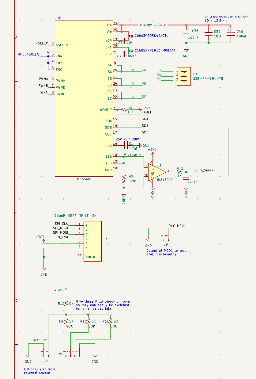
I connected nSLEEP to the MCU, which is running at 3V3. The MP6540H is running at 10V.
ENA, ENB & ENC are joined together and wired to a GPIO of the same MCU. In what follows I’ll call this one connection ENABC.
PWMA, B & C are driven at 3V3 by the MCU using centre aligned PWM mode. These inputs look good on the scope, and they’ve been set up as a slowly moving sin(wt), sin(wt + 120), sin(wt + 240) pattern.
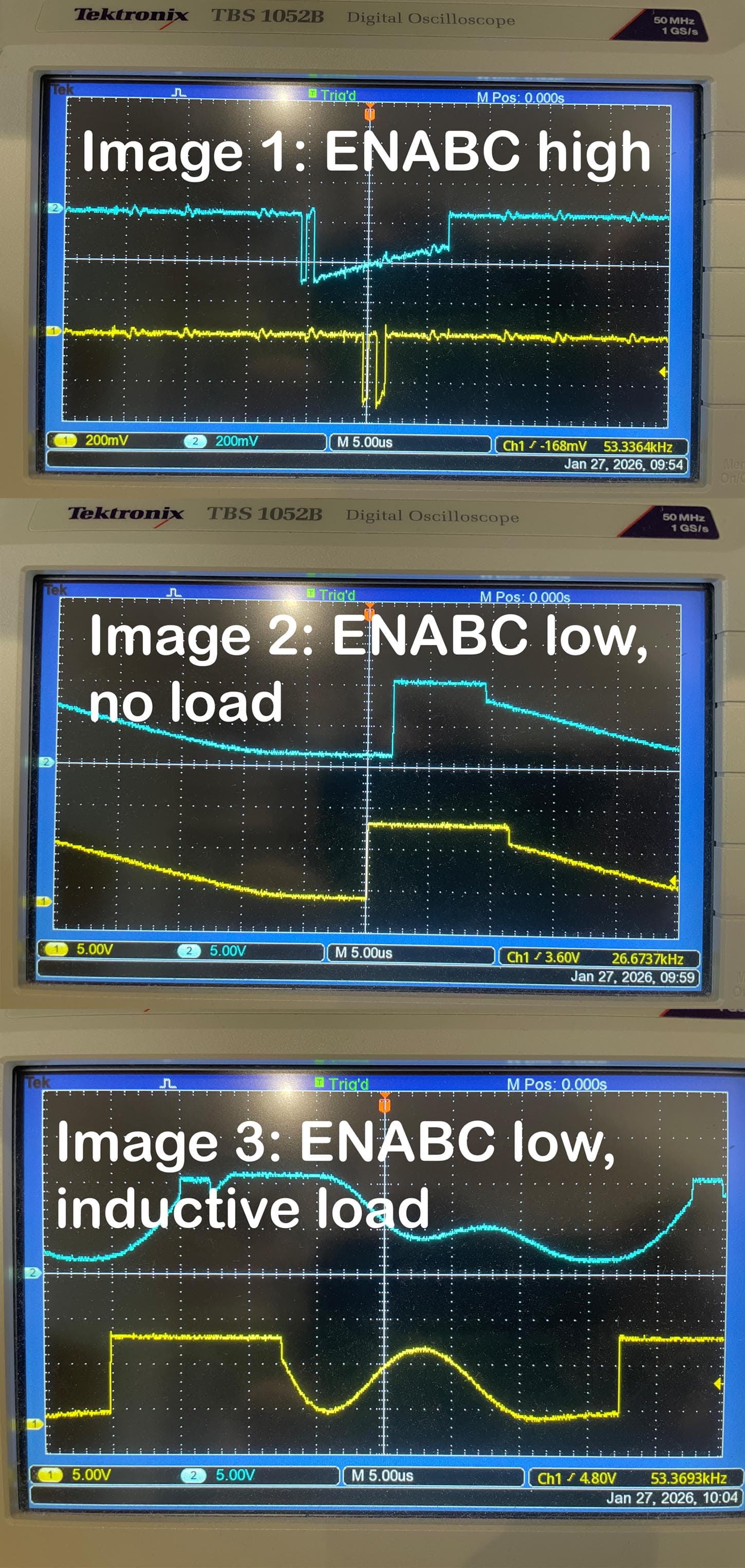
With SLEEPn and ENABC both high, SA, SB and SC are essentially just some noise - see image 1.
With ENABC low (contrary to the datasheet) and no load I see 10V appear at the MP6540H output pins and then decay - see image 2.
With ENABC low and an inductive load (GM5208-12 motor) I see a curvy output voltage - see image 3. There is no current to speak of - my bench supply says it’s supplying 11mA, but the MCU is probably taking a good chunk of that.
I’m really at a loss to understand the behaviour. The normal multimeter poking and prodding suggests that the chip is correctly soldered to the PCB without shorts. I include a portion of my schematic in case it reveals the problem.
Any help would be much appreciated!