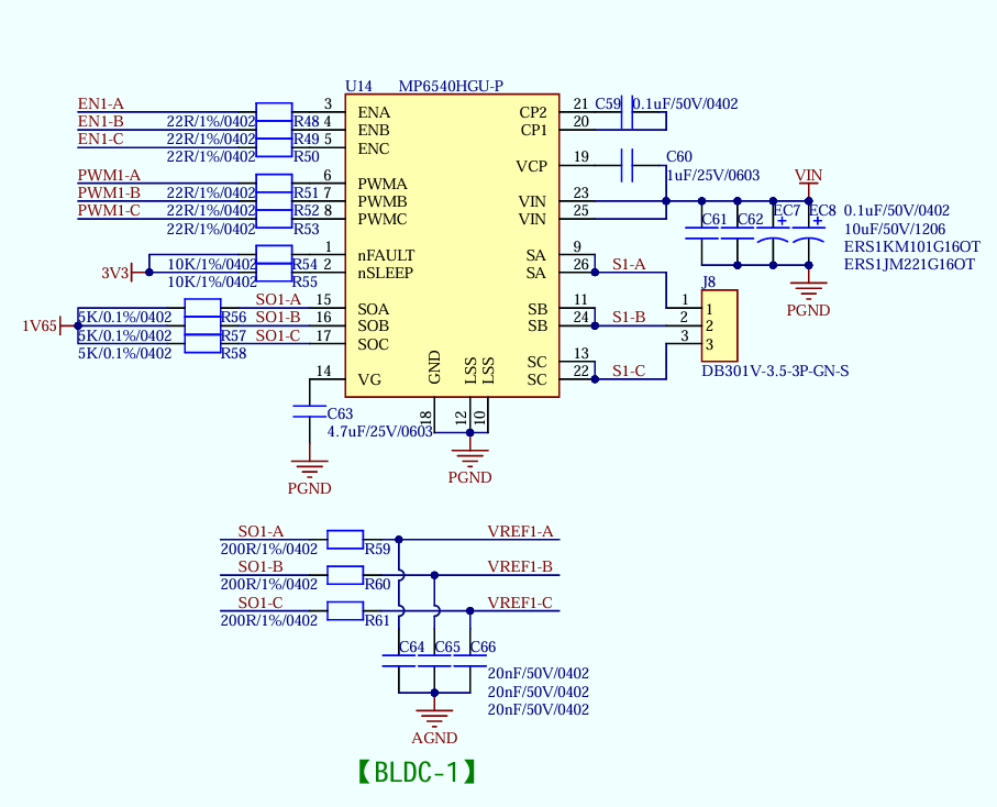
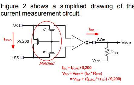
I am using the MP6540 chip to implement the current loop for a brushless motor. When sampling the three-phase currents, I added an RC filter circuit outside the current sense output pins (SOA, SOB, SOC). However, after adding the RC filter, the sampled current becomes very inaccurate as the duty cycle increases. If I remove the RC filter, the current calculation is correct, but there is a lot of noise.
Is it actually acceptable to add an RC filter here? If I do use an RC filter, do I need to change the original formula used to calculate the current? Currently, I am using R = 200 Ω and C = 20 nF, which gives a cutoff frequency of 40 kHz. My current loop bandwidth is 1 kHz, and the PWM frequency is 20 kHz.