Title: MP6538 Evaluation Board Shows ~2A No-Load Current at 24V – Request for Review of Gate and Phase Waveforms
Hello MPS Team,
I am currently evaluating the MP6538 on a custom motor driver board and have encountered an issue with unexpectedly high no-load current consumption.
Test Conditions:
-
Supply voltage: 24V
-
PWM frequency: 25kHz
-
Duty cycle: up to 100%
-
BLDC motor running under no-load condition
Observed Results:
-
Our previous motor driver boards draw approximately 0.15A under no-load operation.
-
The MP6538-based board draws approximately 2A under the same no-load condition.
-
The motor already reaches its no-load speed at approximately 70% PWM duty cycle.
-
Increasing the duty cycle from 70% to 100% produces little additional speed increase, but the input current remains much higher than expected.
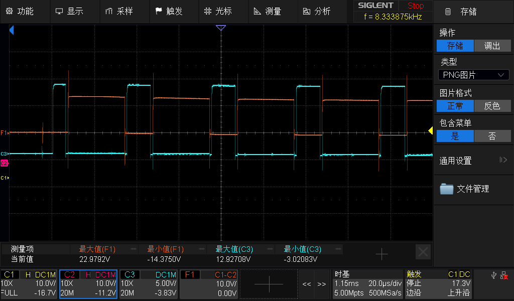
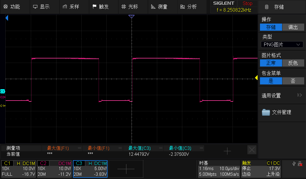
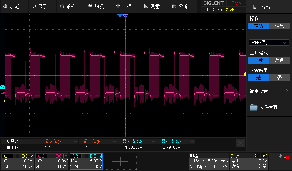
To investigate the issue, I measured the gate drive signals and phase-U voltage waveform.
Waveform Observations:
-
High-side and low-side gate drive amplitudes are approximately 12V–13V.
-
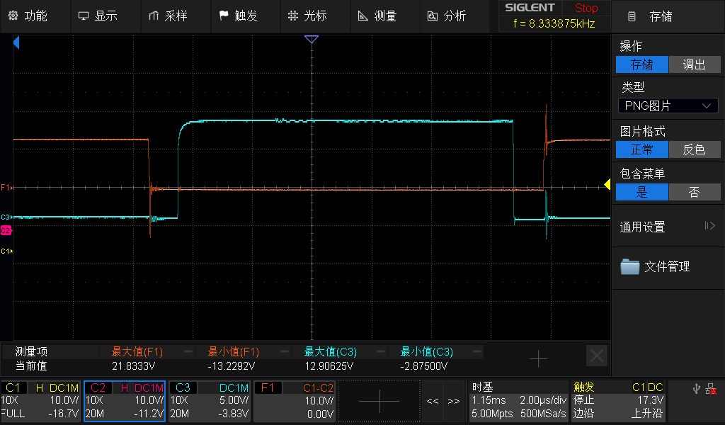
No obvious overlap between high-side and low-side gate signals is observed.
-
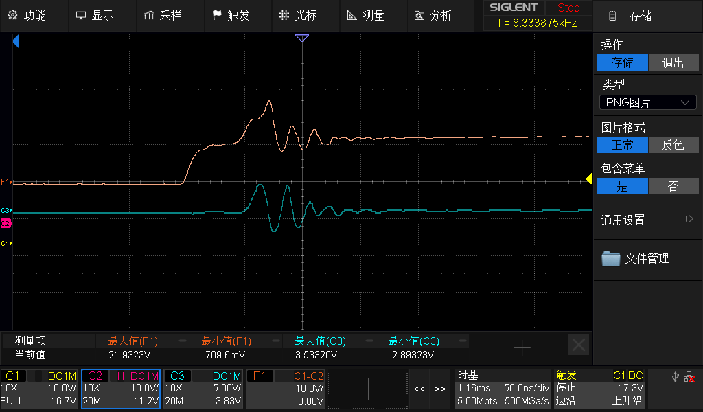
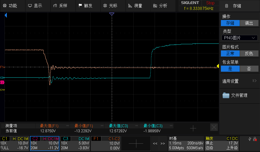
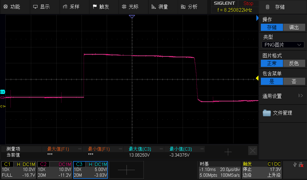
The switching transitions appear generally clean, although some ringing is present during switching events.
-
The phase-U voltage waveform shows expected PWM switching behavior.
-
No obvious abnormal oscillation or gate-drive malfunction is visible from the captured waveforms.
I have attached:
-
High-side gate waveform (Phase U)
-
Low-side gate waveform (Phase U)
-
High-side/low-side timing relationship
-
Zoomed-in switching transitions
-
Phase-U voltage waveform
-
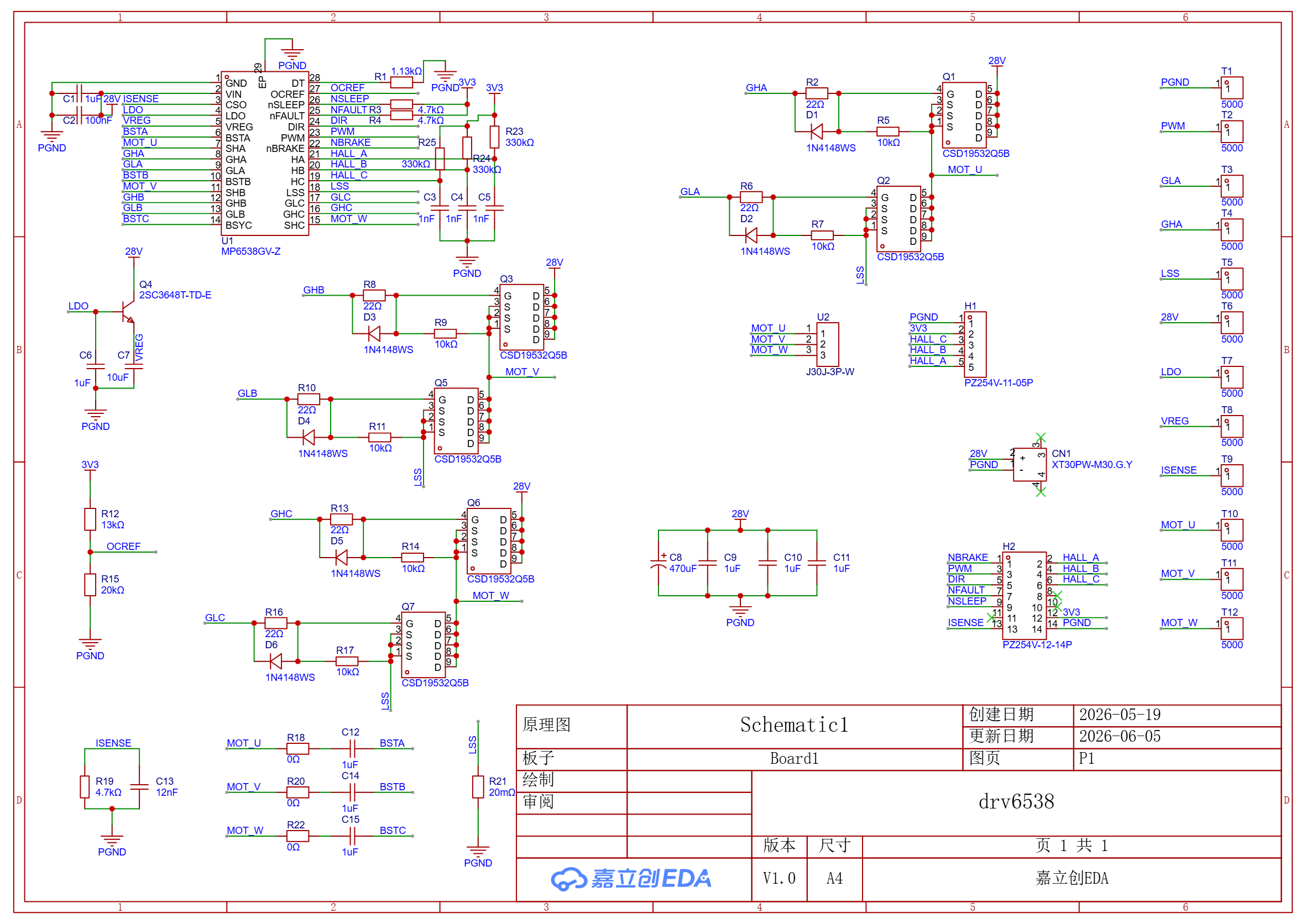
Schematic
My questions are:
-
Is a no-load supply current of approximately 2A expected under these operating conditions?
-
Do the attached gate-drive and phase-voltage waveforms indicate any abnormal behavior?
-
Are there any known MP6538 configuration, layout, or gate-drive considerations that could result in significantly higher no-load current consumption?
-
What additional measurements would you recommend to identify the source of the excess current?
If necessary, I can also provide:
-
Complete schematic
-
PCB layout
-
MOSFET part number
-
Additional oscilloscope captures
Any suggestions would be greatly appreciated.
Thank you.