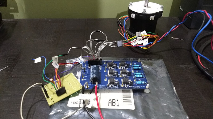
Hi, I’m trying to drive a BLDC motor (12V, 60W @no load) with the MP6532 EV board (EV6532-R00A).
Required control signals are generated using a 8bit microchip controller. I am reading a input supply (Vin) with scale down resistor divider and converting its value to a proportional duty cycle. The PWM frequency is 20KHz. DT is 200kohm and OCREF is 0.2V. Direction pin is pulled high through 4.7k resistance. Gate resistor value increased by adding 20E in series with pre-existing 2E resistance on-board. At power on, break signal is pulled low and released after 500ms. After that pwm is enabled to drive the motor. Input supply given is 13V constant. With these conditions when I am switching the power on, MP6532 is pulling the fault signal down. I tried to debug the issue, and found MOSFET are short.
Further to replace MOSFETs and use external MOSFETs, I disconnected gate and source pins of all MOSFETS by lifting up gate and source pins. Before, adding new MOSFETS externally on board, I tried to check whether IC 6532 is in working condition or not. I found that it is still pulling down fault pin even though output current is zero now. And If I pull down the sleep signal in such condition, fault signal gets released. Can any one please help me how can I debug it further. I also thought that boot strap capacitors will not charge when all MOSFETs are disconnected from circuit. So, I have pulled down all pins SHA, SHB & SHC by using jumpers given on board (JP2, JP5 & JP8). But, still IC is entering in fault mode at each power on as soon as PWM signal is enabled. I am not sure but should I declare that MP6532 has got damaged due to some offend that I could not capture here OR is there any better way to debug and analyze the issue clearly.
Hello Design,
I will take a look into your question and respond as soon as possible.
Thank you,
Vinh Tran
Hey what’s going on,
It looks like you’re triggering the fault mode. Everything is described on page 10-13 of the MP6532 datasheet. Look at “fault mode” then at the block diagram on page 10, it’s triggered from overcurrent, overtemperature, AND undervoltage. Now look at “startup sequence”, it says it’s not ready to take inputs and drive transistors for up to 2 milliseconds while vreg is charging up. Now look at UVLO protection, it says it monitors VIN and VREG, and if VREG drops below the low voltage threshold under any circumstance, it latches the fault pin active low. Think of what actions could cause VREG volts to fall below the threshold.
Even though you maintain a constant vin, you need to also obey the startup sequence and let VREG charge for 2ms. You said it yourself that on startup you immediately set the nBrake pin to low. By doing that, you’re attempting to discharge vreg to charge / turn on all of the low-side MOSFETS. It then follows that after 500ms you bring the active low nBrake pin high (normal operation) and later toggle sleep mode and everything works. It works because after sleep, you obeyed the startup sequence and allowed VREG to charge without running nBrake or any other inputs. The chip enters startup after each sleep so it needs to come with a 1-2ms delay each time.
This issue was probably frustrating and driving you to pursue extreme measures, but I would take pause before modifying the evaluation board, lifting gate / source pins and other physical mods, that would really increase your chances of damaging the chip. Try and post to the forums first to get an expert response (hopefully within a month, lol). But worse case you just need to drop in a replacement Mp6532 and worst case a trace got torn and you need to run a wire to make the broken connections. Hopefully neither of those are a reality.
Appreciated your clearly stated starting conditions and control signal states, that made troubleshooting and responding easy.
Thanks for your reply on this post.
Yes, pulling down the break signal at power on would be creating above issue.
But now, I have already developed my own PCB rather than continue using evaluation board, as I had to scrap it after doing many experiments with it.
And now I could run the motor with new PCB. But still in this case also I did face below problem.
Here, If I apply the PWM duty cycle in step change of 0 to 40% or higher, MP6532 goes in to fault mode. But if I increase duty cycle gradually from 20% to 95% in about 20 steps keeping 10-20 msec delay between consecutive steps then it works fine. Same logic I have to follow to stop the motor (i.e. gradually decrease the duty cycle from 95% to 20% and then 0).
Below inputs for your reference =
1] Before applying PWM signal, I have kept 500msec delay after power is switched on to consider rise time and startup sequence
2] Sleep, DIR & Break signal are permanently pulled up to 5V. (Not interfaced to controller).
3] Dead band resistor value is 470 Kohm.
4] OCP reference set at about 0.225V
5] LSS pin shorted to ground.
6] Vreg capacitor value 10uf ceramic, Bootstrap cap value= 0.68uf,
7] Decoupling caps placed close to pin
8] Motor is run at no load condition, (It takes leass than 2Amp @12V dc)
9] MOSFET Rdson is 5.1 miliohm max
10] Gate charge 68nC
11] Gate resistor value used 20ohm
And I have followed recommended PCB layout guidelines as per datasheet.
Hello all,
When it comes to deeper level discussions, it is best to submit a ticket through this link.
Regards,
Jonathan Hidalgo
