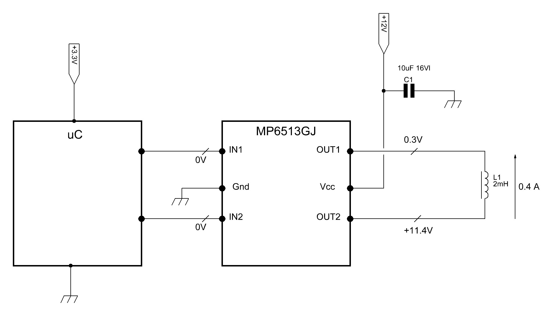
Hi, I have MP6513GJ ,it work at 12Vdc.The range for input pins is 0-3.3VDC. I noted in some cases,statically, i have IN1 at 0V, IN2 at 0V and at same time i have OUT 1 to GND and OUT 2 at +12V,then the coil output is powered…I thik with Inputs both at 0 V , i must to have OUT1 and OUT2 at high impedance… Where is my error? Thanks in advance…
Hello,
The Input range for the MP6513 is 2.5V to 21V. It would also help further narrow down this issue if you had a schematic to show here?
Let me know.
Best,
Krishan
I think if i have 0V in IN1 ,and 0V in IN2 ,i must don’t have output current…
Then? Now schematic is here… ![]()
The situation I showed in the schematic does not happen always, but occasionally after doing many switches on the inputs.
You question here makes sense. When IN1 = IN2 = 0V, then OUT1 = OUT2 = High Z.
It is possible there could be leakage currents or parasitic paths. Could this coil hold charge and cause some small current circulation? Once the outputs go to High-Z, the energy charged in the coil may not go away previously. Conversely it would be worthwhile to check if there is some leakage in the FETs for leakage when they are nominally off. Both these routes would need some compensation for sure.
In your schematic, are the pins driving 1N1 and 1N2 have pull down resistors? Are the lines clean with no noise or floating? If the inputs bounce briefly around threshold voltages, there is a chance the driver may activate one H-bridge side.
Let me know if there are any updates.
Best,
Krishan