Hello,
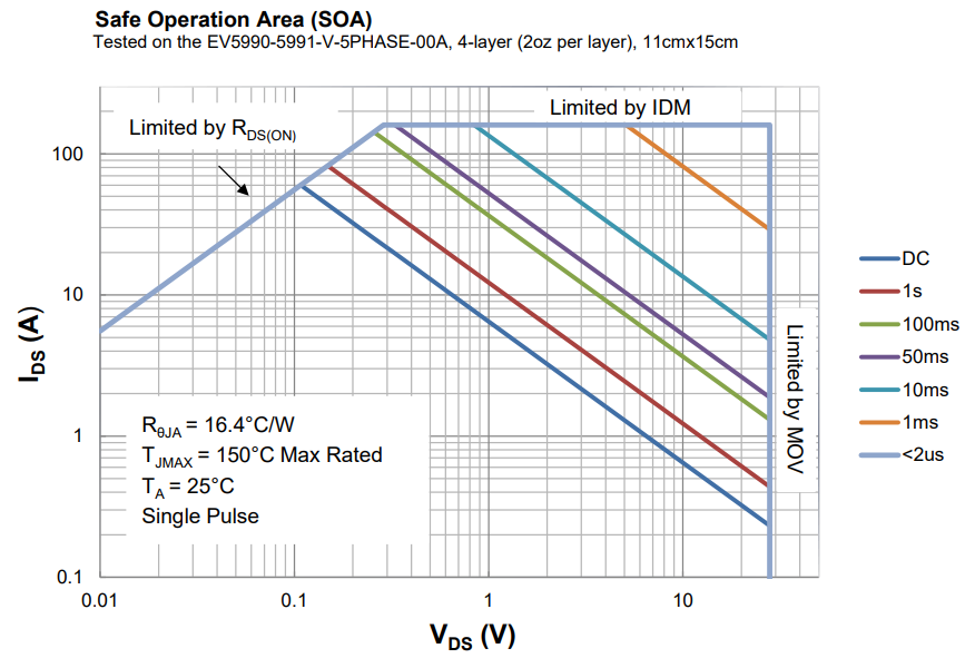
I’m looking at the SOA curve for the MP5990 and MP5991 and have a question for my application. I plan to use this IC to control the 12V DC input into a device. The max DC current is around 35A for my application. When I look at the SOA curve on page 14 of the datasheet, the Ids limit seems to be set at 8A for the lowest Vds values. Once the 12V switch is activated, the rail should always be on. Am I interpreting this device incorrectly for my application. I guess the sloped Blue line in the plot is really what I should be paying attention to, but that’s in the 100s of mV range, not the 35mV I expect. Also, what does the 50A continuous current quoted in the datasheet mean if Vds on is typically in the tens of mV range. Any other comments would be appreciated and please let me know if I’m interpreting something incorrectly. It seems I need to double up on these parts for my application or use a external FET hot-swap controller.
Thanks,
Tony