HI MPS expert,
When power failure occurs, MP5515 can only run in buck mode, but can’t run in boost mode ,right?
That means the backup storage capacitor only can transfer the energy to the set VB, will stop transfer when Vbackup < VB?
in order to improve the storage energy utilization efficiency, should set the VB to lower volatge?
Hi Allen, welcome to the forum!
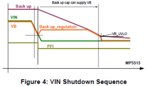
Correct, while the input is stable the MP5515 will be in a boost mode to generate a high voltage on the storage capacitor. Then if the input shuts down, the device switches to buck mode and steps the storage capacitor voltage down to transfer energy to the bus and holds the bus voltage while the system consumes the energy from the storage capacitor.
Because of this, the VB bus voltage will always be less than the value of the storage caps as they are discharged.
I’m not sure what you mean by the storage energy utilization efficiency, but you should set VB to a level that allows your circuit to operate during this last dying gasp of energy.
Hi Allen, welcome to the forum!
If the input shuts down, the device switches from boost mode to buck mode and steps the storage capacitor voltage down to transfer energy to the bus and holds the bus voltage. You would better set VB to a level that allows your circuit to operate during this last dying gasp of energy.
For more details, please send emails to Daniel.Yang@monolithicpower.com
HI Kareem,HI Daniel,
THanks for your support.
In our design: VIN=12V, we want to set the Vstorage=30V
if set the VB =12V, the buck converter will stop working when Vstorage reach 12V, do it mean there is much energy can’t be used?
If set the VB=5V, the storage energy can be used till to Vstorage=5V, the storage energy utilization efficiency will be improved, right?
Hi Allen, the image I attached in the previous reply does a good job of illustrating the flow of energy during the last gasp. Imagine the voltage on the backup capacitor as the new VIN for the system during the last gasp. This voltage is being bucked down by the converter to supply the bus voltage.
If the Vin droops down to the level of the regulation voltage set point, then the buck converter will simply track the input voltage down until it triggers the UVLO (which I believe is 2.35V).
If the VB is set lower, there will be more time before this occurs, but I don’t necessarily think it would be an issue. Regardless, as long as you set the voltage high enough to power your downstream circuitry long enough for it to run its critical operations you should be fine.
HI Kareem,
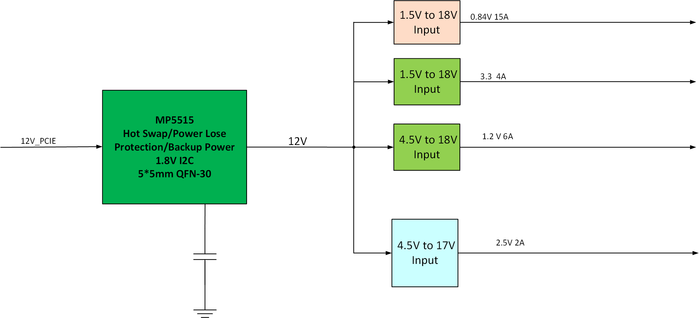
Our power tree design is as below.
the downstream DC/DC minimum input is 4.5V, if we set the VB=5V, does it means we can get more time to do the operation than setting VB=12V?
When Vin drops down to the the level of the regulation voltage set point, the buck converter should start to work to covert the Vstorage to VB, why you said: the buck converter will simply track the input voltage down until it triggers the UVLO
Hi Allen, if you want to set the Vb to 5V that should be fine. Vb will regulate at the set point for a longer amount of time as you have noted.
HI MPS expert,
We have a requirement to control the system power off, but need the buckup power work at this situation. We want to just use a signal to connect MP5515 EN pin to realize this purpose.
But we are worried that the IC will not work included the backup power when EN is low.
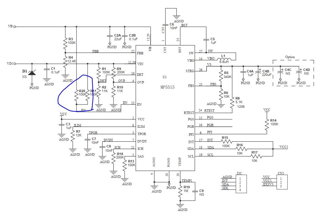
Because we noticed the EN pin is pull up to both VIN and VB in your EVM board. When VIN drops, the EN still can keep High due to VB existing.
Please comment it.
Thanks
Although the EN still can keep High due to VB existing when VIN drops, the MP5515 pulls PFI low internally to indicate a power failure since DET drops below 0.99 x VDET-REF, Simultaneously, the MP5515 exits boost mode no matter EN status. If the DET voltage rises to 1.02 x VDET-REF, PFI is set to high again (if pulled up by a resistor externally), but the MP5515 does not exit buck mode, even if PFI is high, until the VSTRG energy is discharged to UVLO or the IC resets.
Enable Control (EN)
The EN pin of the MP5515 works together with the EN bit to enable the internal circuit. The MP5515 is enabled after both the EN pin and EN bit are high. When EN is low, the MP5515 is forced to buck mode until VSTRG is discharged. Thus, EN-off is one of the conditions to start power back-up stage. The IC power back-up function will also work when EN is low.
Ok. understand that MP5515 will run into buck mode when EN=low ntil VSTRG is discharged.
then if the EN goes high, will the IC run into normal status?
Thanks
When EN is low, the MP5515 exits boost mode and is forced to buck mode until VSTRG is discharged. Then if EN goes high during buck mode, the MP5515 does not exit buck mode. The MP5515 restarts automatically as a new power on cycle with a TPOR process after the buck stops (VB triggers VB_UVLO).
- I still don’t undserstand this decription clearly:
The MP5515 restarts automatically as a new power on cycle with a TPOR process after the buck stops (VB triggers VB_UVLO).
Can you please share more details about it? - If VIN is always ON, when EN low time is enough long to let VSTRG discharged fully, and then EN goes high, what will happen? VB can recover to norm status?
- What is the purpose of the pull-up resitor to VB in your EVM board? can be removed?
Actually, we want to understand if VB can be simply controlled ON/OFF by EN pin (VB need have power from VSTRG when EN low)?
Thanks
If VIN is always ON, when EN low time is enough long to let VSTRG discharged fully, and then EN goes high after PLP BUCK stops, the MP5515 restarts automatically as a new power on cycle. MP5515 can recover to normal status. The pull-up resistor from EN to VB in EVM board can be removed. You could control the ON/OFF of ISOFET by EN pin or EN bit in corresponding resister.
Your datasheet describes the EN voltage can’t be higher than 6.5V, but your EVM board connect it to VIN=12V, why? is it ok just to guarantee the EN current <1mA even if it pull up to 12V?
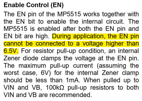
We recommended 100kohm pull-up resistors when connecting EN to VIN or VB, since there is clamping circuit internally. The actual EN voltage will be lower than 5V. During application, EN pin voltage need be lower than 6.5V when pulled up to a higher voltage through a resistor. Internal clamp circuit will clamp EN voltage down to around 5V if sink current is lower than 1mA.
The energy in a capacitor is 1/2V^2 so the energy in a cap at 12V is(12/30)^2 about 16% of the original energy. You aren’t leaving that much on the table
But your EVM board pull EN up to VIN=12V directly. Can we also pull it up to 12V and ensure the sink current is less than 1mA?
Thanks

Sorry for confusion. you mentioned:
But your EVM board pull up to 12V, so my questin is : can we pull up to 12V through a 100K resistor? or we must need pull EN up to voltage lower than 6.5V?
Thanks
Hi, Allen
Although EN pin is pulled up to VIN and VB through 100kohm, there is clamping circuit internally. Internal clamp circuit will clamp EN voltage down to around 5V if sink current is lower than 1mA. So, the actual EN voltage on EVB will be lower than 5V.
During your application, I recommend you pull up EN to a voltage lower than 6.5V through a pull-up resistor.