Hello Support Team,
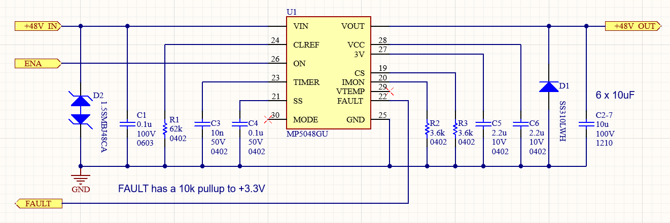
I am trying to understand why an MP5048GU failed in a controller. (partial schematic attached) A controller passed initial testing then failed during a later test. Some controllers with the same design continue to work. Others have failed during testing or after. I’ve verified that at least one PCB has a failed MP5048GU. My client is shipping me a few more PCBs with similar symptoms to diagnose.
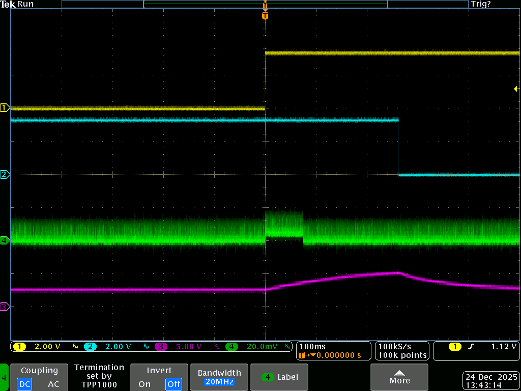
The attached scope capture shows pin 26 ON (trace 1), pin 22 FAULT (trace 2), pin 19 CS (trace 3) and VOUT (trace 4). It looks like, when enabled, the internal FET delivers very little current. The limiter logic then detects a problem and disables. With a current probe, I verified that an insignificant amount of current flows from the 48V bench supply.
Typically, on enable, the only load is the six 10uF caps. However, it’s possible that it could be several amps. During operation, the average current is a few amps with brief (<1ms) peaks of up to 6A. The load can return current to the 48V input at a similar amplitude. This could also occur for about 1ms as the MP5048GU is disabled with a low at the ON pin or due to a fault. In this case, the current would return through the MP5048GU FET body diode. It’s possible the body diode current could be higher, and it’s not limited by the MP5048GU. The load has a residual voltage of about 3V with the MP5048GU disabled.
Any ideas as to the cause of the failure would be appreciated. And let me know if there are tests I can do that would be helpful.