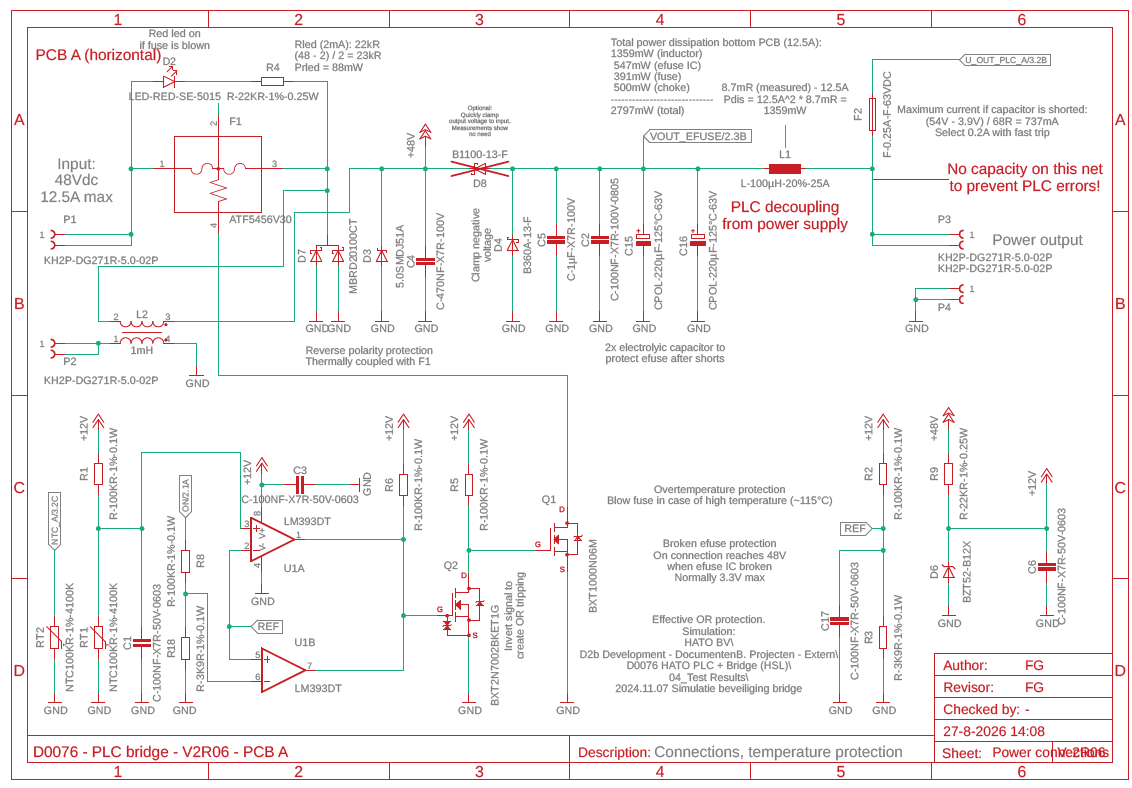
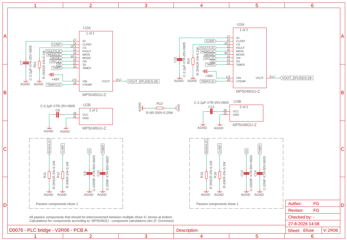
We are using the MP5048GU in a design to protect output after a 600W/48Vdc power supply. 2x IC’s are placed in parallel. Previous design survived a hard short on output without problems, in new design a common mode choke was added and all other components are the same. PCB layout was also altered because of new component.
PCB used is 4 layer. Previous version was with MP5048GU IC produced in 2024, new version is with IC produced in 2026, other component differences seem to be ruled out so far. What could be the cause for damaged IC during our tests and how can we assure components survive these kind of tests?
V2R05 schematic (this survives repeated hard shorts):
(same as V2R06, only without L2)
V2R06 schematic (this typically already damages efuse after 1 short):
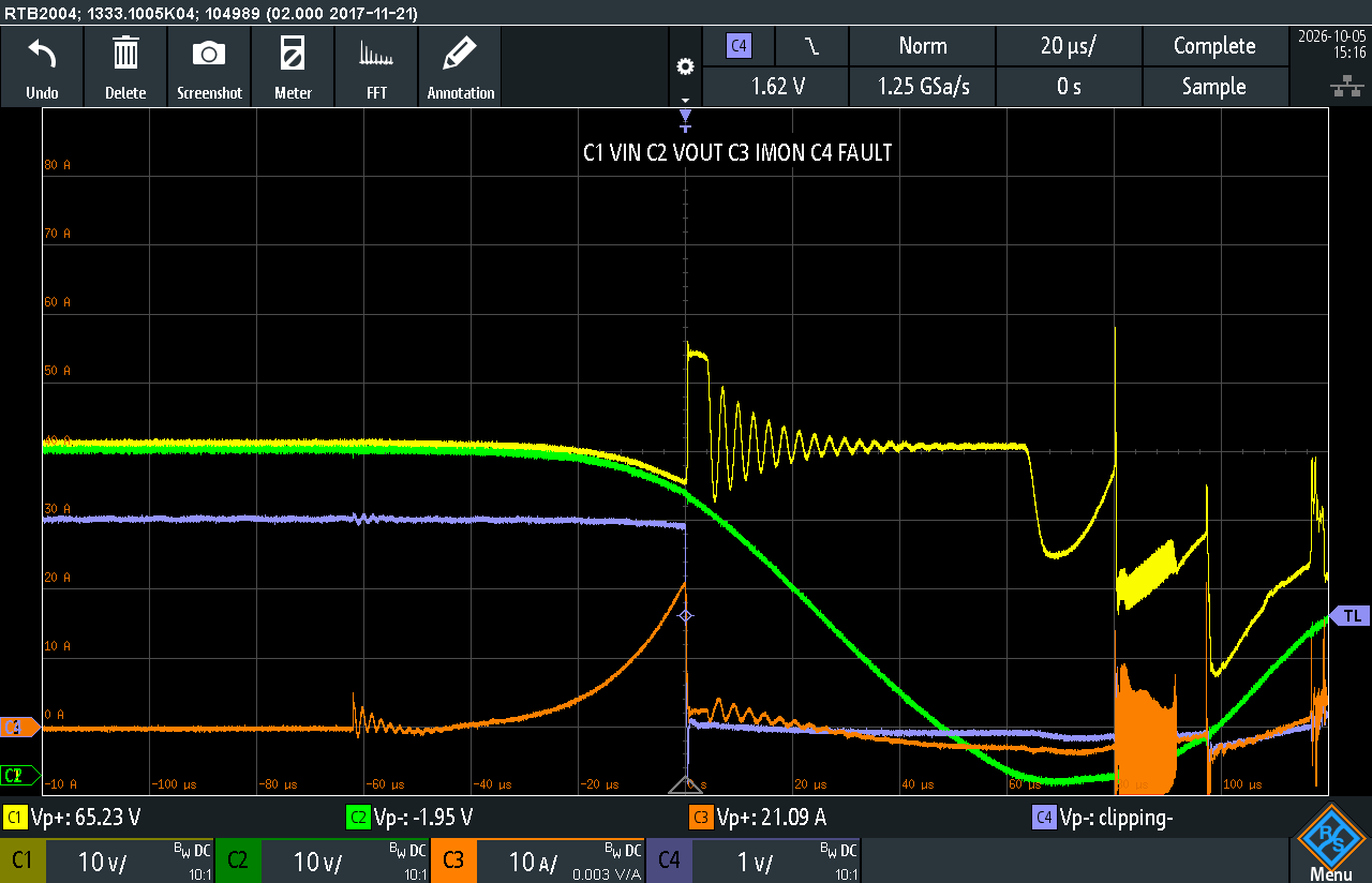
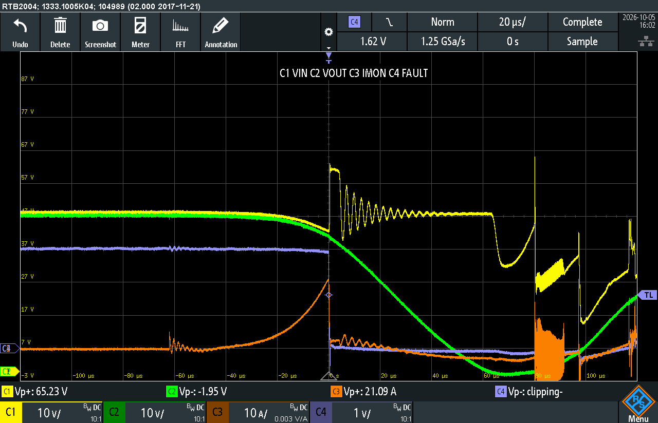
Oscilloscope recording of hard short:
For the new design, have you tried testing the design without the common mode choke? If you are still facing issues, this could be a layout issue. If the PCB trace between the choke’s input and output is unintentionally connected, or if the design uses a bypass path that shorts the choke when it’s removed, it can appear as a short.
Additionally (considering the common mode choke still on the board), how widespread is this issue? The reason why I ask is because this could be an assembly issue where if the common mode choke was attached backwards in the opposite polarity, the two windings can be connected in a way that bypasses the inductance and effectively shorts the supply.
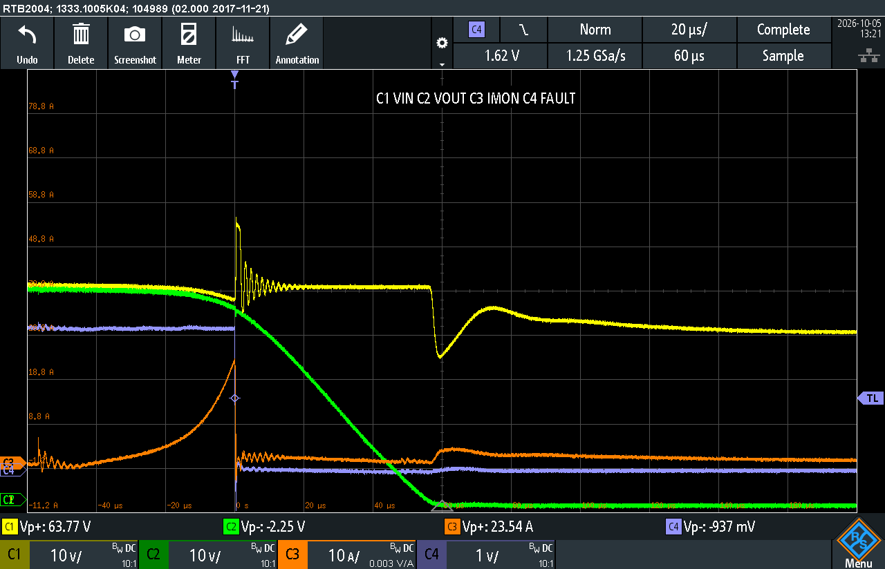
I also tried the same PCB without the common mode choke. It was shorted on both sides. This also gave the same result:
Other difference was I used output caps with higher ESR, but I also tested with placing the original output capacitors from earlier design with 13mR ESR, this also gave blown efuse IC:
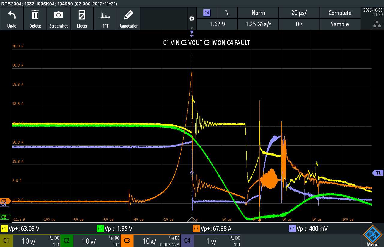
Waveforms (until VIN collapses) lookse quite similar with earlier design which survived hard short:
Only input ringing is somewhat longer with this setup.
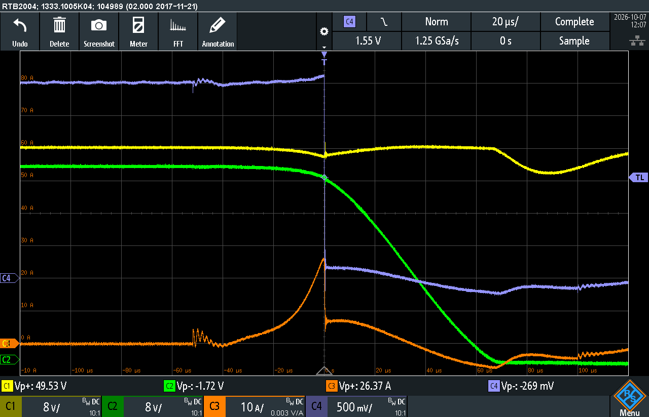
After some more testing, adding an input capacitor before efuse vin seems to protect efuse ic sufficient and eliminates input ringing (100~2220µF).
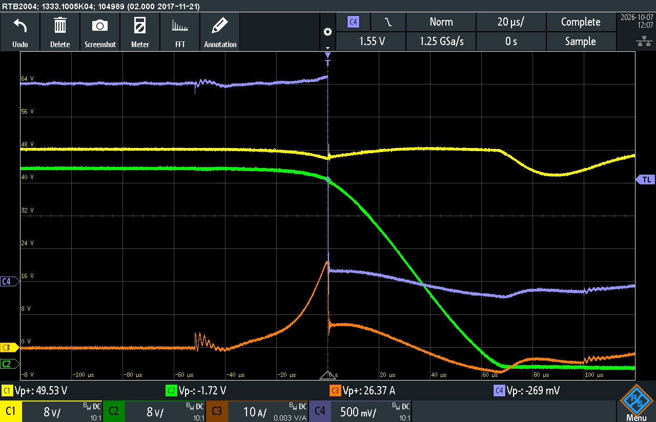
I also tried heavier Schottky diodes on output to limit negative voltage, but this has no measurable impact. Do waveforms below look healthy for a short event?
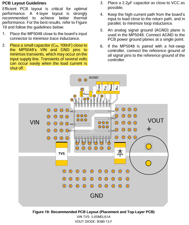
The smoothed-out waveforms where you added your Cin before the E-Fuse looks significantly better. I believe this is even recommended in the PCB layout guidelines for the MP5048 in order to minimize any tranients:
Please ensure that you are following all other guidelines as shown. I would recommend that you keep testing any edge cases to confirm the feasibility of your setup.