Hi,
I am currently working with the MP5031 USB Power Delivery controller on my project, and facing an issue where Power Delivery (PD) negotiation does not seem to initiate when I connect a PD tester. I use MP5031 standalone without any DC-DC chip and I can control the registers of MP5031 through I2C and MCU.
Here’s a summary of the situation:
-
Connected the MP5031 to a USB Type-C cable and attached a PD tester to the port.
-
Upon connection, the tester does not show any signs of a successful PD handshake, and no PD messages (e.g., SOURCE_CAP) are detected by the tester. It says “A correct CC attachment is detected, but no source_cap is received in time”
-
The MP5031 appears to detect the cable insertion correctly, but no PD negotiation takes place.
Could you please assist in diagnosing what might be causing this issue? Do I need to make some register configuration during boot up ?
Thank you for your time and support.
Any thoughts ? would be appreciated
Apologies for the delayed response here. I have the following questions to narrow down the debugging process:
-
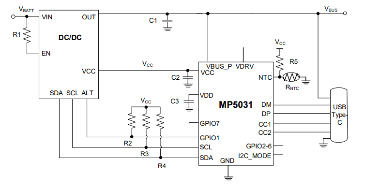
Is Vbus and VCC powered within the default input range? The datasheet specifies a 3.3V - 21V range for Vbus and a 4.5V - 5.5V range for VCC. I have seen connectivity issues from the Vbus and VCC voltages not being within range or in some cases not powered at all for VCC. Since you are using this IC without a DC/DC converter, this usually supplies VCC as seen by the typical application:
-
How is the MP5031 configured during boot-up via I2C? When checking the SOURCE_CAP register, are you initialized?
-
Verify that CC1 and CC2 are properly terminated to the USB-C cable. While this is a simple hardware issue it is always good to check. If possible, verify with an oscilloscope to confirm CC communication during insertion.
-
The error message indicated a timeout for SOURCE_CAP. Ensure that you are responding within the required PD Timing window. Check any timeout settings related to SOURCE_CAP.
Hopefully this provided some insight. I hope to hear back from you soon with progress on debugging. I know I threw a lot at you but go down the list one at a time and go from there.
Best,
Krishan
Thanks Krishan,
Voltages seems in a normal range and the boot-up sequence is :
write 0x0C 0xDA08
write 0x0B 0x1081
write 0x0C 0x5A08
write 0x00 0x0208
Do you have a suggested boot-up register settings ? There is a bit named SEND_SRC_CAP
in CTL2 register for example what should I set this value to ?
Here is a general initialization for enabling PD negotiation.
-
Enabling the PD Controller with boot sequence as you have done.
-
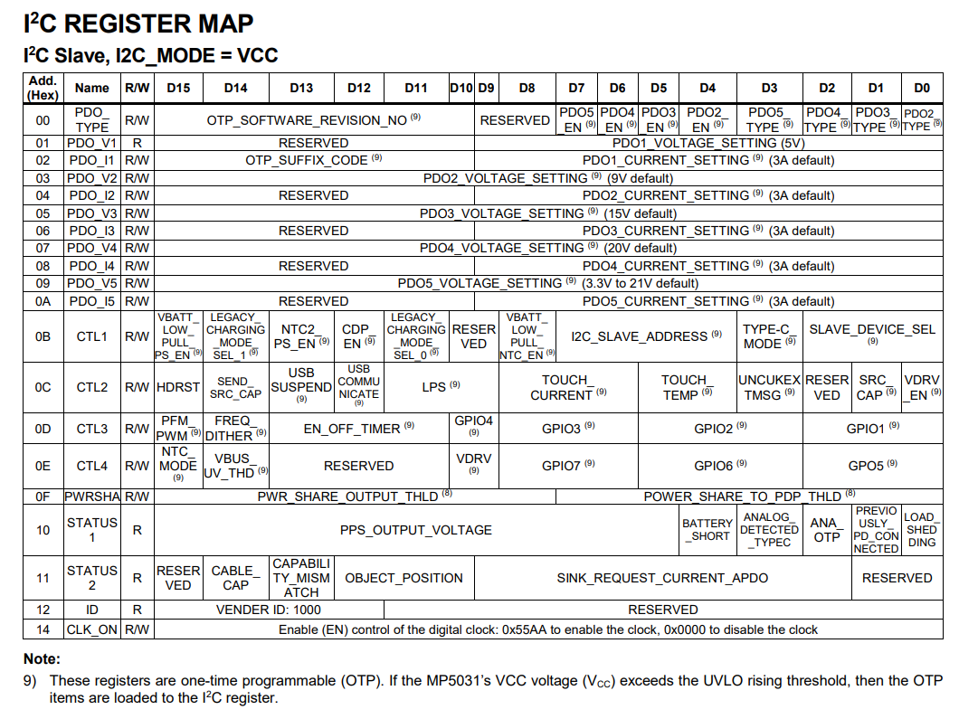
Configuring Source Capabilities in terms of your desired voltage and current levels. Here is an overhead on what that looks like (25):
-
Setting SEND_SRC_CAP to 1 as it is set low by default. Here is a description of what this entails in CTL2 for bit 14 (page 31):
Hope this provided some insight. Let me know if there are any more questions.