Hello, From the simulation below that R6 is calculated to be 100K and R7 is 4.64K. How do I ensure that no more than 150uA is sink into the EN pin?Please advise
)
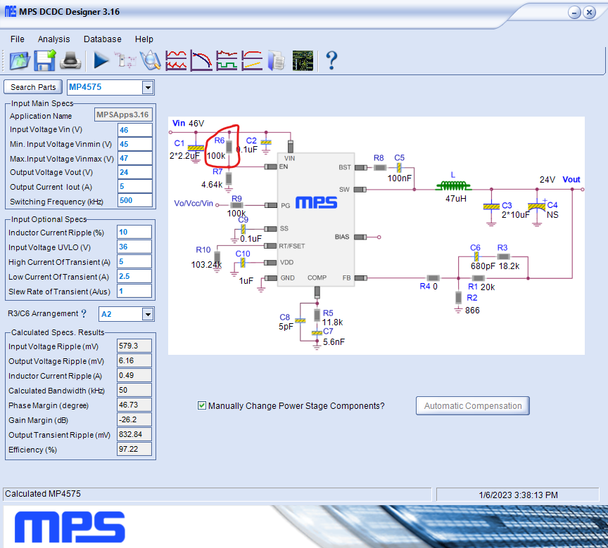
Hello, From the simulation below that R6 is calculated to be 100K and R7 is 4.64K. How do I ensure that no more than 150uA is sink into the EN pin?Please advise
Hi dphan -
Thank you for utilizing MPS Technical Forum,
Resistance value above 300k should work to ensure EN current is below 150uA. You may also refer to the typical applications circuit in the datasheet for reference on pg 21.
Regards,
Nouman
Hi Nouman, I tried 300K but the device would not turn on. Please advise
Hi dphan -
Can you please confirm the following:
Per the datasheet:
Drive EN higher than 1.6V to turn on the regulator; drive EN lower than 1.3V to turn off the regulator.
Kind Regards,
Nouman
I would break out the Fluke and measure the voltage at the pin. Maybe you have a wrong component.
So let me ask it again. What are the resistor values to ensure no more than 150uA is sink into the EN pin? The simulation proposed circuit shows R6=100K and R7=4.64K. How to determine the sink current into EN is under 150uA using R6 and R7 values?
My circuit is the same as the simulation above. 46V is the input. The resistive divider network is same as the simulation above that is R6=100K and R7=4.64K. My original question was not about the voltage to turn on or off the device. I was asking about the 150uA sinking current into EN pin. But you suggested to change R6 to 300K which I did and the device is disabled. I changed it back to 100K so the device is enabled. Please advise on the 150uA sinking current question as it related to R6 and R7.
Alright bear in mind that I am just some internet weirdo, but if you look at the internal diagram of the chip you will see that there is a zener diode internal on the pin. Lets suppose it is 6V as that is the maximum voltage allowed on the pin. Your voltage divider 4.6k/100k gives you 2 volts at 46V in. In this case the zener won’t conduct the voltage at the pin is under the maximum allowed for the pin, there is no problem. You don’t have to worry about the second part of the rating ( 150uA) in the case where the EN voltage exceeds the internal zener voltage. Do you have a curve tracer? You could for fun use a limiting resistor on a power supply and inject voltage/current into the EN pin and characterize the VI behavior of the pin. You could see when the zener broke over.
Thank you much for detail explanation. It makes sense to me now. thanks again