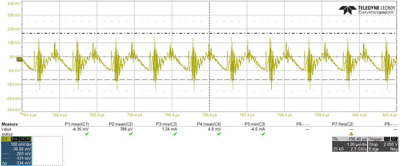
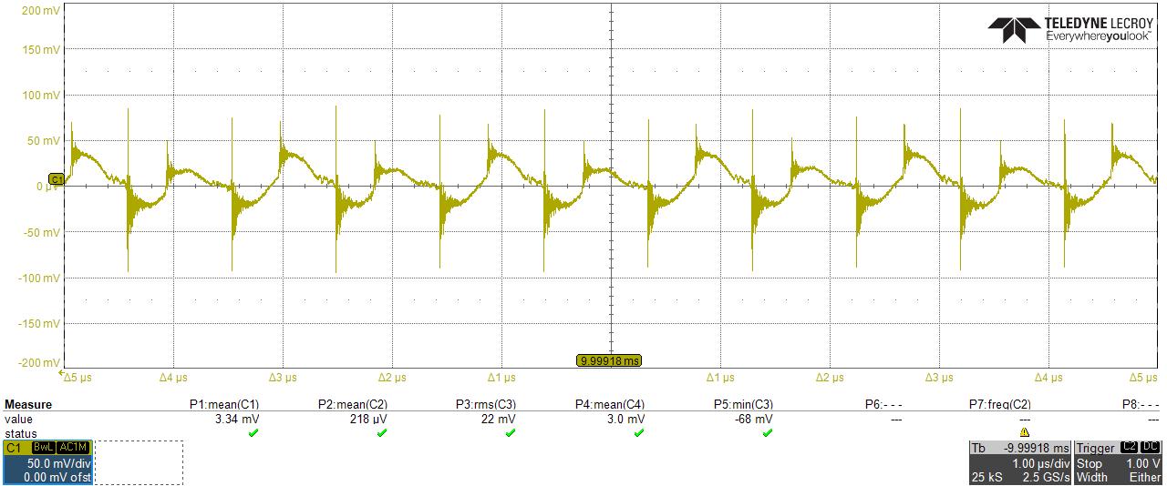
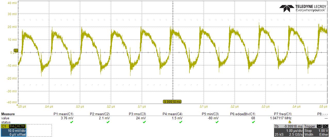
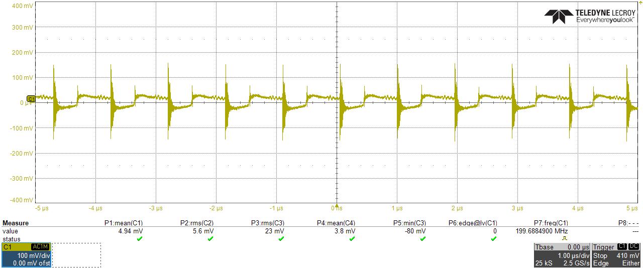
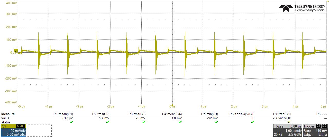
I am using an MP4562 on a PCB to convert 48 V input to 19 V output (position 2). However, I am observing significant noise on the output at around 1 MHz. The switching frequency is set to 1 MHz, but there appears to be considerable ringing at each switching event plus the triangular signal amplitude seems too high.
This noise is affecting the proper operation of my system, and it increases with the load current.
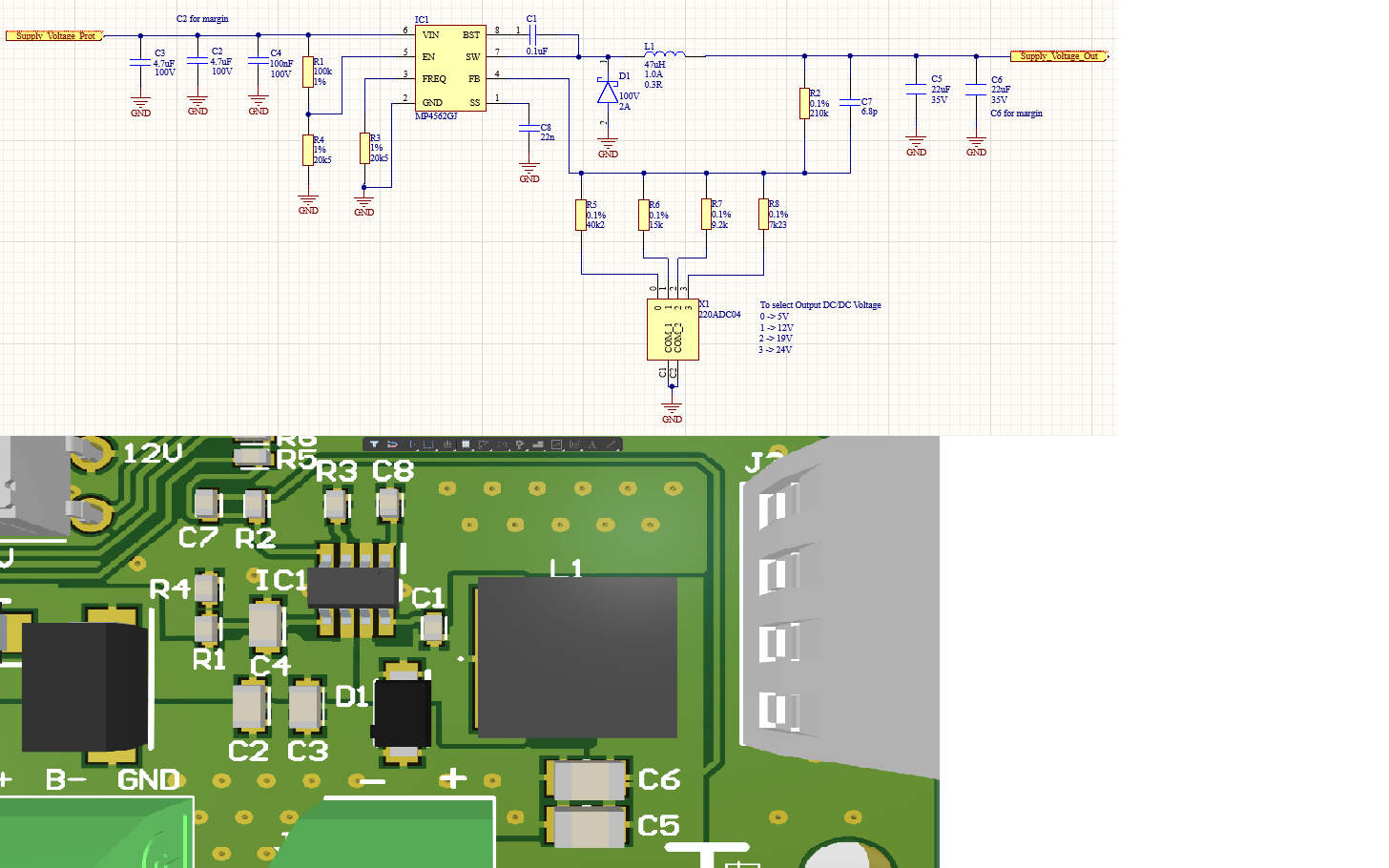
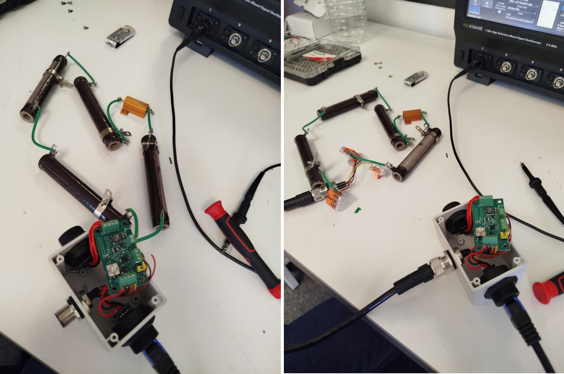
I have attached the schematic, PCB layout, and oscilloscope measurements. For the measurements, I powered the board using a laboratory power supply and probed the output. The output is connected to a 62 ohms load here.
I am unsure whether the selected components (especially the diode => PMEG10020ELRX) are appropriate, and I would appreciate any advice on how to improve the output signal quality and reduce the ringing.
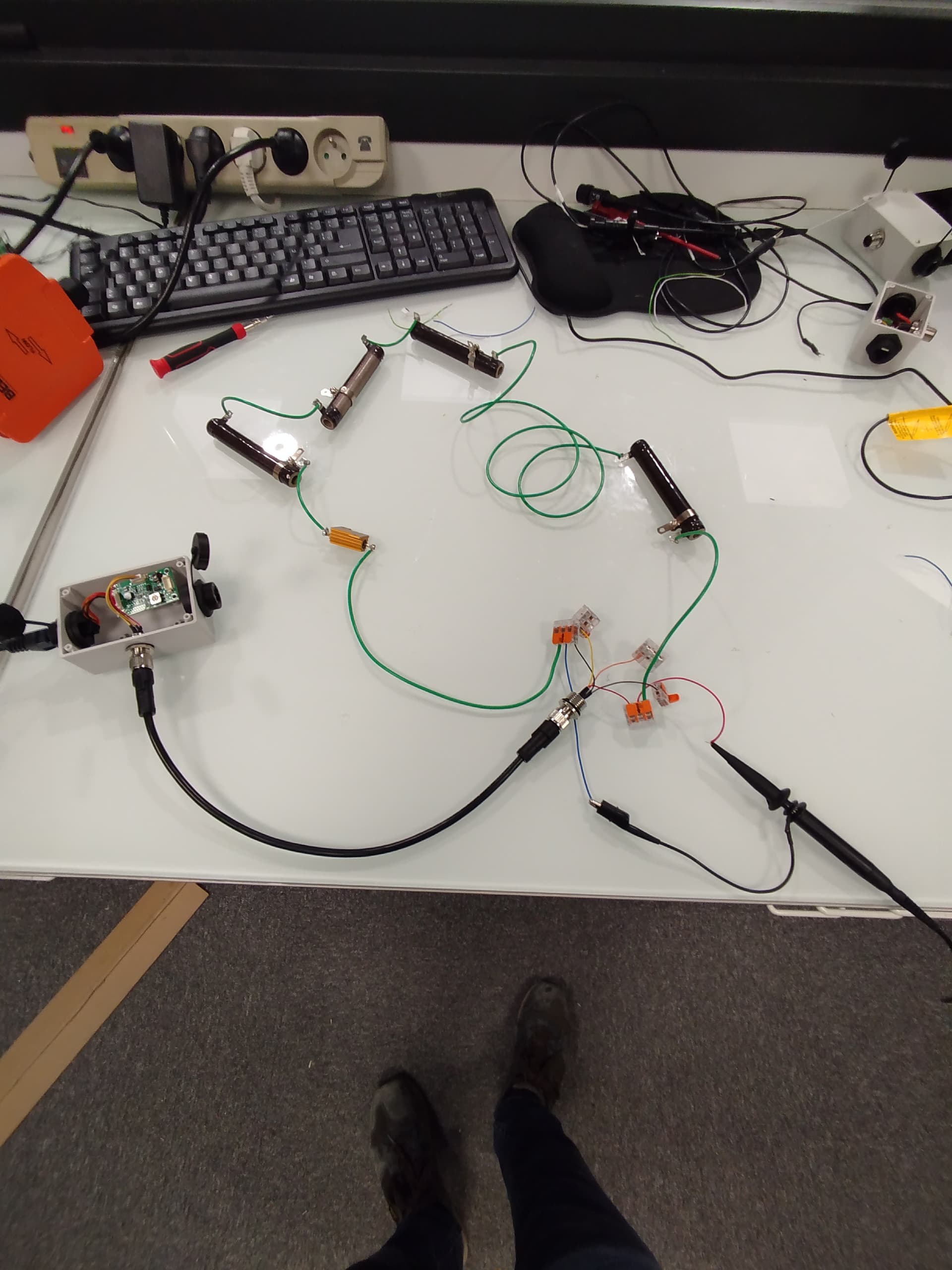
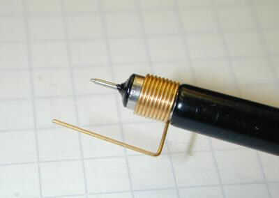
I believe the biggest source of noise could be coming from your long wires. What’s your application, and does it require the long wires? If possible, can you try using shorter wires? We can first start with shortening the ground loop of your probe and measuring across C6, then across the 62ohms load (try using a tip & barrel method as shown below):
I currently do not have a ground spring for my probe, but I plan to get one soon. The output voltage is 19 V, so the current should be around 300 mA with that resistor.
I will also try to shorten the measurement wires.
In my application, this DC/DC converter powers another electronic board (not shown in the picture I previously shared). A pump is connected to that board through another DC/DC converter (same model) providing 12 V.
However, a significant amount of noise seems to be present on both the power line and the communication signals, at least based on my oscilloscope observations. I replaced the pump with a resistive load, but the issue remains.
The 1 MHz switching signal is visible almost everywhere I probe, along with the ringing. I am currently trying to isolate the root cause of the issue.
While you are adjusting the wire lengths, can you isolate the MP4562 board and probe across C6, with and without having 62ohms load (solder the resistor on top of C6)? From here we can test to see if the noise is coming from the IC, or if it’s related to the wires.
I used a ground spring with my probe, shortened the wires, and repeated the measurements. The signal amplitude is lower with the ground spring, but the waveform remains quite similar.
Here are my two setups: