I have a newer design with MP4559 that has a ripple in addition to the 3V3 DC signal at the output when load is added.
The more load, the higher is the ripple.
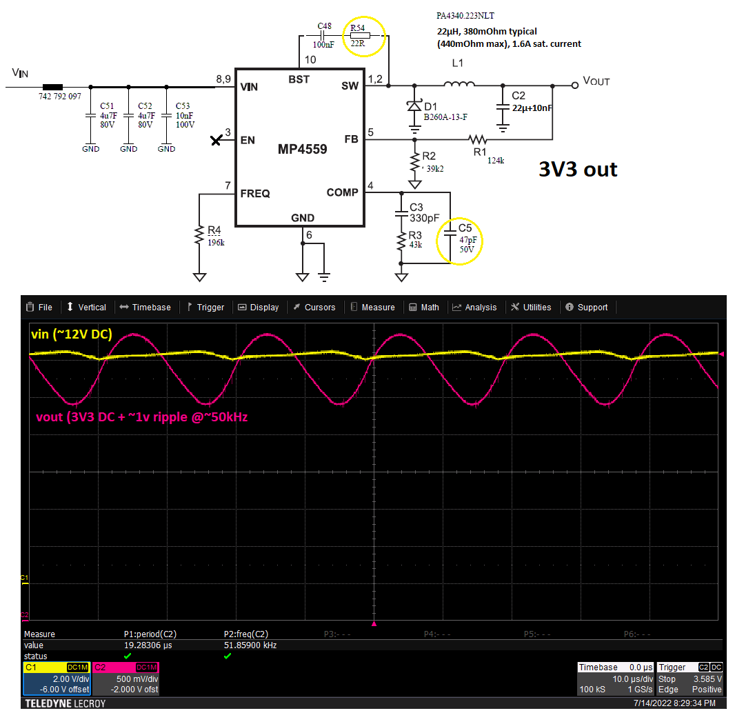
In the picture we see: used schematic with highlighted differences to suggestion in datasheet. Output and input of 3V3 DC-DC-converter at higher load with the mentioned ripple. The ripple can be eliminated by removing C5.
We use this schematic in several designs with lower loads, and we had never a problem. But with this design we use 8 relais at 3V3 and the inductive load may not be compatible with the compensation network.
Anyhow, the ripple can be reduced by removing C5 and this is the part I have problems with understanding.
Is it possible that the C5 component is responsible for the ripple?
Are there other ressources / more infos than datasheet to define the compensation network?
The load of 8 relais is of course < 1,6A 
thanks!
Hello,
Welcome to the forum!
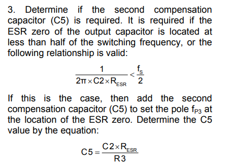
You can refer to the below paragraph for requirement of C5 and if its needed in your application or not.
Basically, it will affect the control loop of the part and thus you are seeing more ripple.
Let me know if you need anymore help.
Regards,
Yash Shah
Well as the philosopher David Hume explained causality is when the mind believes that one thing leads to another. So if every time you add the cap the thing oscillates we start to say the one thing causes the other. The why of it? Oh lots of math and theory about poles and zeros, or possibly a layout error. I would suggest more output C as a random guy from the internet.
hi, and thanks for helping out!
My feeling says that i used the term “ripple” in a wrong way. I would tend to speak from a instability issue more likely.
Using C5 or not depends on the ESR value of output cap. My feeling says that the used 0603/10V 22F MLCC Cap has a very low ESR, but i don’t know at the moment. My feeling says that a C5 can not prodce a instability and we have another problem here. But i will investigate on that.
But let me shed light on the maths side and look at the facts:
We are using 497 kHz (R4=196k) switching frequency and with the actual setting the crossover frequency is about 209 kHz (R3=43k, C2=22µF) what would be way to high choosen (datasheet says"A good rule of thumb is to set the crossover frequency to approximately one-tenth of the switching frequency"), what do you think?
I will try to adjust the R3 to set to f_c=f_sw/10 (or increase f_sw) , increase output cap C2.
Reducing f_c forces me tu use a increased C3 according to the formulars.
Does these steps make sense to you?
Is there any step by step docu for the problem? I am not afraid of the maths
Hello,
Yes, it is advisable and a good practice to use fc=fsw/10. You can play with the passives to get it closer. Sometimes, there is a difference between what we calculate and what we end up seeing on the board due to parasitics involved.
Your calculations are correct, I think. But, do you really need C5 if you are using ceramic output caps?
Regards,
Yash Shah
thanks, you helped me a lot.
The C5 is now not-populated and the output C is higher. Both reduced the output ripple.