I am using the MP4323 in a gas generator control circuit. VOut is set to 5v and the load is a 5v hobby sized servo, an MCU, a CAN ic, an ADC ic, and a few other small components. The MCU is fed by a 3v3 LDO while the other IC’s receive the 5v from the MP4323. The main current draw from everything minus the servo is typially around 150-200ma. The servo draws marginal power when not moving but can spike up to around 2400ma if it stalls.
The problem i am having is my CAN Ic, mcp2562, kept dying on me. So i scoped the 5v power supply to see if that was the cause and noticed that when I engage the generator starter motor, the battery voltage drops to ~8 volts and then slowy creeps closer to 11v. When this happens there is a spike on the output of the MP4323, usually around 6.5-7.5v but i saw a few spikes around Vin level(nominal 12v).
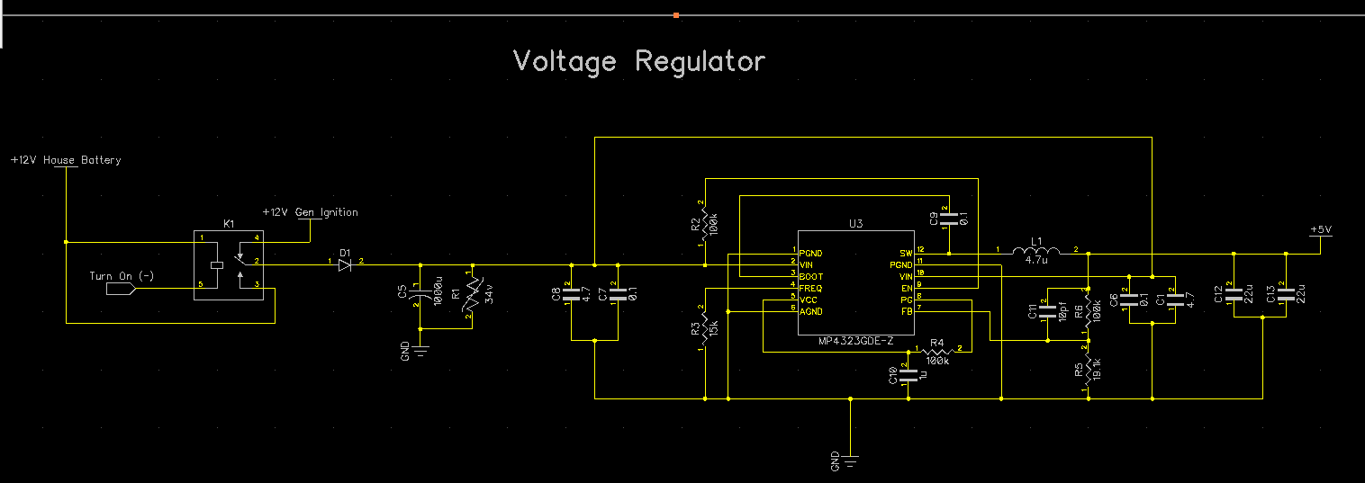
I followed the diagram in the datasheet using component sizes for a 5v, 3a load to give me some buffer. That is 4.7uf x 2 and 0.1uf x 2 input capacitors, 22uf x2 output capacitors, and 4.7uh molded inductor Fsw is 2.2mhz. i am using name brand quality x7r MLCC caps. I also have a bulk electrolytic of 1000uf right at the Vin of my PCB.
What would cause these short voltage spikes that are frying my CAN transceivers? Most of the time the current draw from the MP4323 is low, but the max can be close to 3a so I chose those values. I tried to keep feedback trace away from the switching node. Any help would be appreciated.
Hi ahawn615,
Can you share your schematic and layout with us to review so that we can have a clear picture of your circuit design?
Have you connected the bootstrap resistor+ capacitor on the switch node?
Are the spikes seen for a minimal amount of time or it is staying consistent at any input voltage you apply?
Regards,
Adhish
Thank you for getting back to me,
The spikes seem to only happen when the voltage dips when the engine starter engages. I have the bootstrap capacitor in place but no resisto.
I do not have a photo of the scope output at them moment.
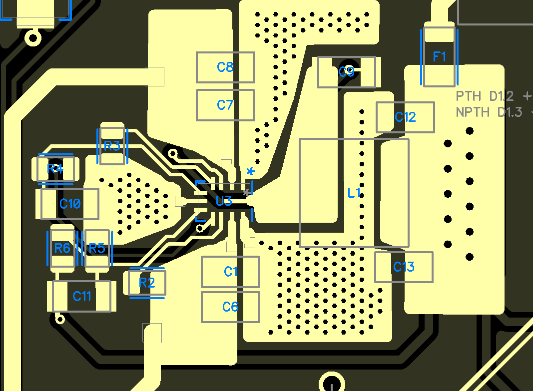
Here is the schematic and PCB layout,
Hi ahawn615,
Thanks for sending this over. I will review this from my end and will get back to you.
Regards,
Adhish
Hi ahawn615.
The schematic and layout looks good overall, however the spikes can be possibly due to the number of output capacitor and the chosen inductor value for high frequency (2.2 Mhz).
When you were testing, did you captured the waveforms for Vout, Vin, IL and SW? If so, then kindly share those as well
In the meantime, I would suggest to do the following things from your end and see if this issue is still there.
- Adding an additional 2-3 number of output capacitors from 10uF -22uF, keeping L1 = 4.7uH to check if the spikes still exists at load/no-load
- Replace L1 with 1uH or 2.2uH keeping C11 at load/no-load
- Replace L1 with 1uH or 2.2uH removing C11 at load/no-load
Also, Input bulk cap of 1000uF looks very high to me. Something upto 50uF - 100uF should be enough.
Let me know if you have any concerns with the measurements.
Regards,
Adhish
This topic was automatically closed after 9 days. New replies are no longer allowed.